

Organic electroluminescent element, lighting device and display device
a technology of electroluminescent elements and lighting devices, applied in the direction of luminescent compositions, thermoelectric devices, chemistry apparatus and processes, etc., can solve the problems of deteriorating the light emission lifetime of elements, and achieve excellent thermal stability, excellent stability, and excellent stability
Inactive Publication Date: 2015-06-25
KONICA MINOLTA INC
View PDF6 Cites 12 Cited by
- Summary
- Abstract
- Description
- Claims
- Application Information
AI Technical Summary
Benefits of technology
The present invention provides an organic electroluminescent element with good thermal stability, excited state stability, and carrier conduction stability. The element uses an organic material that has a satisfactory light emission spectrum and high efficiency and long service life. The invention also provides a light device and a display device that use the organic electroluminescent element.
Problems solved by technology
However, an organic EL device that utilizes phosphorescent luminescence is significantly different from an organic EL device that utilizes fluorescent luminescence, and thus, the method for controlling the position of the luminescence center, particularly the question of how stably light emission can be achieved by inducing recombination inside the light emitting layer, has become a critical technical problem for securing the efficiency and service life of an element.
However, since the light emission lifetime of elements is deteriorated thereby to a large extent, an improvement in the trade-off is demanded.
Method used
View moreImage
Smart ImageViewing Examples

Examples
example 7
Compound Example 7
[0128]
example 9
Compound Example 9
[0131]
Login to View More PUM
 Abstract
Provided is an organic EL element configured to have at least one organic layer including a light emitting layer interposed between a positive electrode and a negative electrode, in which the light emitting layer contains an iridium complex compound represented by any one of formulas (1) to (4), and the maximum emission wavelength of the iridium complex compound is 470 nm or less.
Description
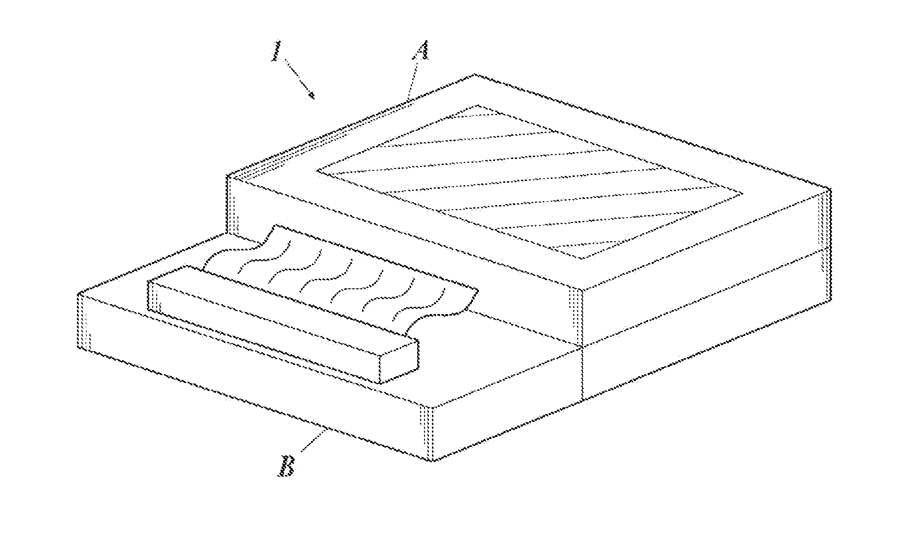
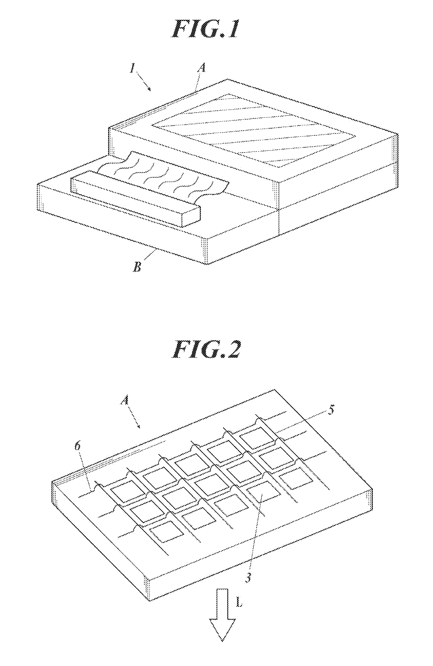
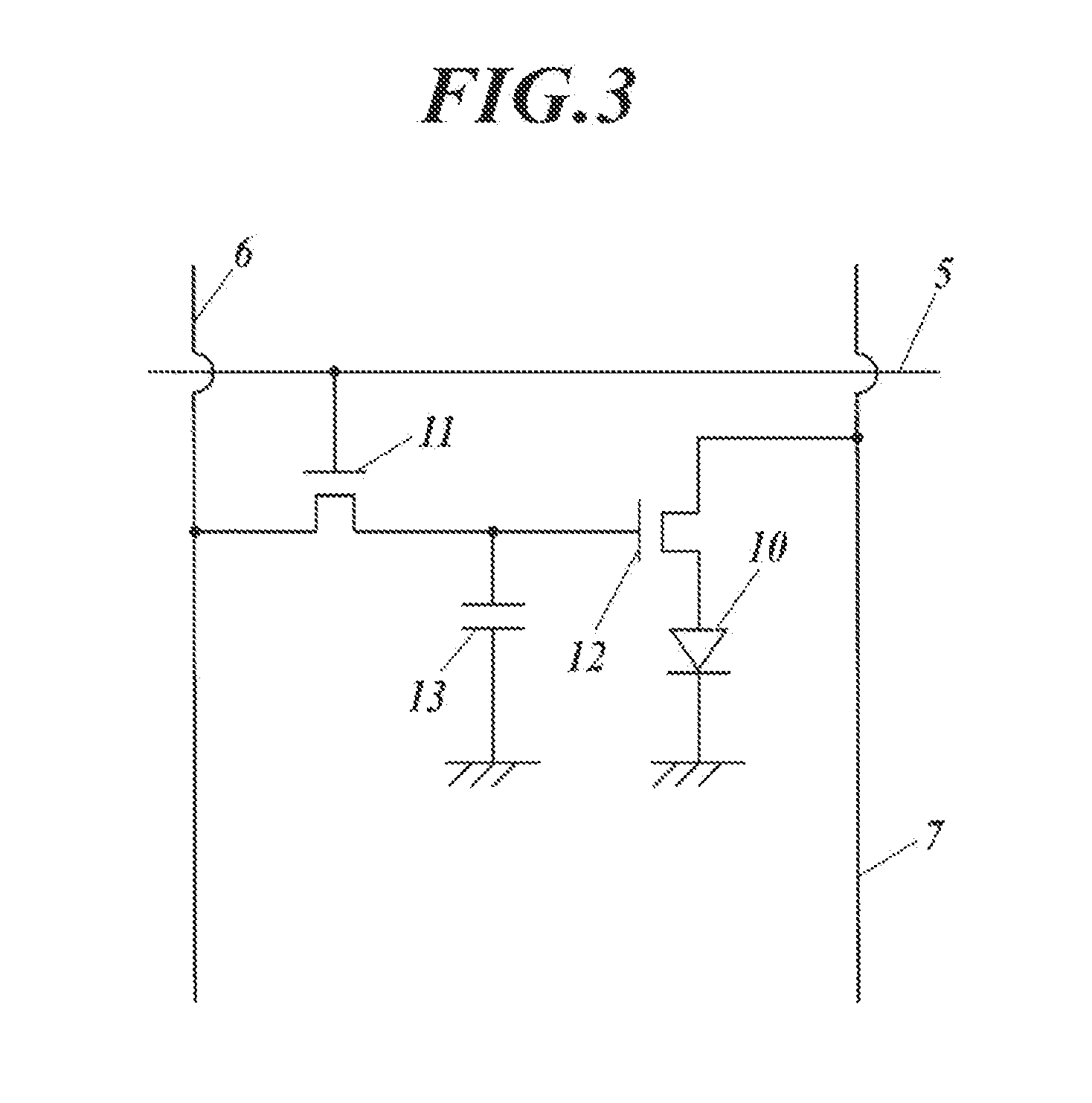
TECHNICAL FIELD[0001]The present invention relates to an organic electroluminescent element, a lighting device, and a display device.BACKGROUND ART[0002]An organic electroluminescent element (hereinafter, also referred to as organic EL element) is a light emitting element which is configured to include a light emitting layer containing a luminescent compound between a negative electrode and a positive electrode, and which produces excitons by allowing the holes injected from the positive electrode and the electrons injected from the negative electrode to recombine within the light emitting layer when an electric field is applied, and utilizes the emission of light occurring when these excitons are deactivated (fluorescence / phosphorescence). Furthermore, an organic EL element is an all-solid element constituted by films of organic materials having a thickness in the order of submicrons only, interposed between an electrode and another electrode. Since organic EL elements are capable ...
Claims
Login to View More Application Information
Patent Timeline
 IPC IPC(8): H01L51/00H01L27/32
CPCH01L51/0085H01L51/5012H01L27/32C09K11/06C09K2211/1011C09K2211/1029C09K2211/1044C09K2211/1088C09K2211/185H10K85/631H10K85/6574H10K85/342H10K85/6572H10K50/11H10K2101/10H10K59/879H10K59/00
InventorOTSU, SHINYAKATOH, EISAKUHIKIME, MAYUKA
OwnerKONICA MINOLTA INC