Chemical mechanical planarization apparatus and methods

Active Publication Date: 2015-07-02
SEMICONDUCTOR MANUFACTURING INTERNATIONAL (BEIJING) CORP +1
View PDF19 Cites 14 Cited by
  • Summary
  • Abstract
  • Description
  • Claims
  • Application Information

AI Technical Summary

Problems solved by technology

However, the multiple-layered layout technique may cause the surface of the silicon wafer to be uneven, and it may deteriorate the formation of the patterns, such as devices, and struct

Method used


Image

  • Chemical mechanical planarization apparatus and methods
  • Chemical mechanical planarization apparatus and methods
  • Chemical mechanical planarization apparatus and methods

Examples


Embodiment Construction

[0016]Reference will now be made in detail to exemplary embodiments of the invention, which are illustrated in the accompanying drawings. Wherever possible, the same reference numbers will be used throughout the drawings to refer to the same or like parts.

[0017]As a consumable supply of a CMP process, a polishing slurry may have a significantly important effect on the planarization results of the CMP process. The polishing slurry may normally consist of polish particles and chemical additives, etc. A microscopic view of the CMP process may include a chemical process and a physical process. During the chemical process, a chemical reaction may happen between the chemicals in the polishing slurry and the to-be-polished layer on a wafer; and easy-be-removed products may be produced by the chemical reaction. During the physical process, physical scratches may happen between the polishing particles and the to-be-polished layer; and the products from the chemical process may be removed. Th...


PUM

PropertyMeasurementUnit
Fractionaaaaaaaaaa
Fractionaaaaaaaaaa
Timeaaaaaaaaaa

Abstract

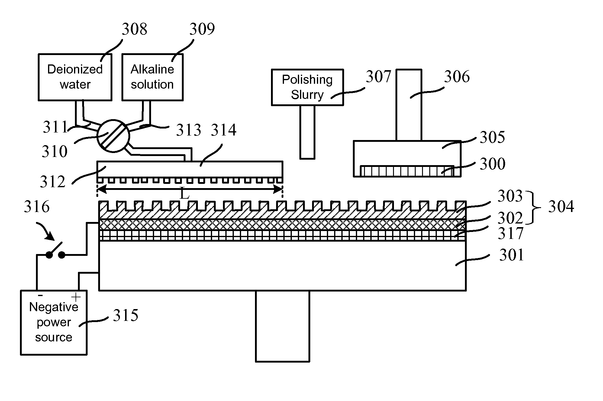
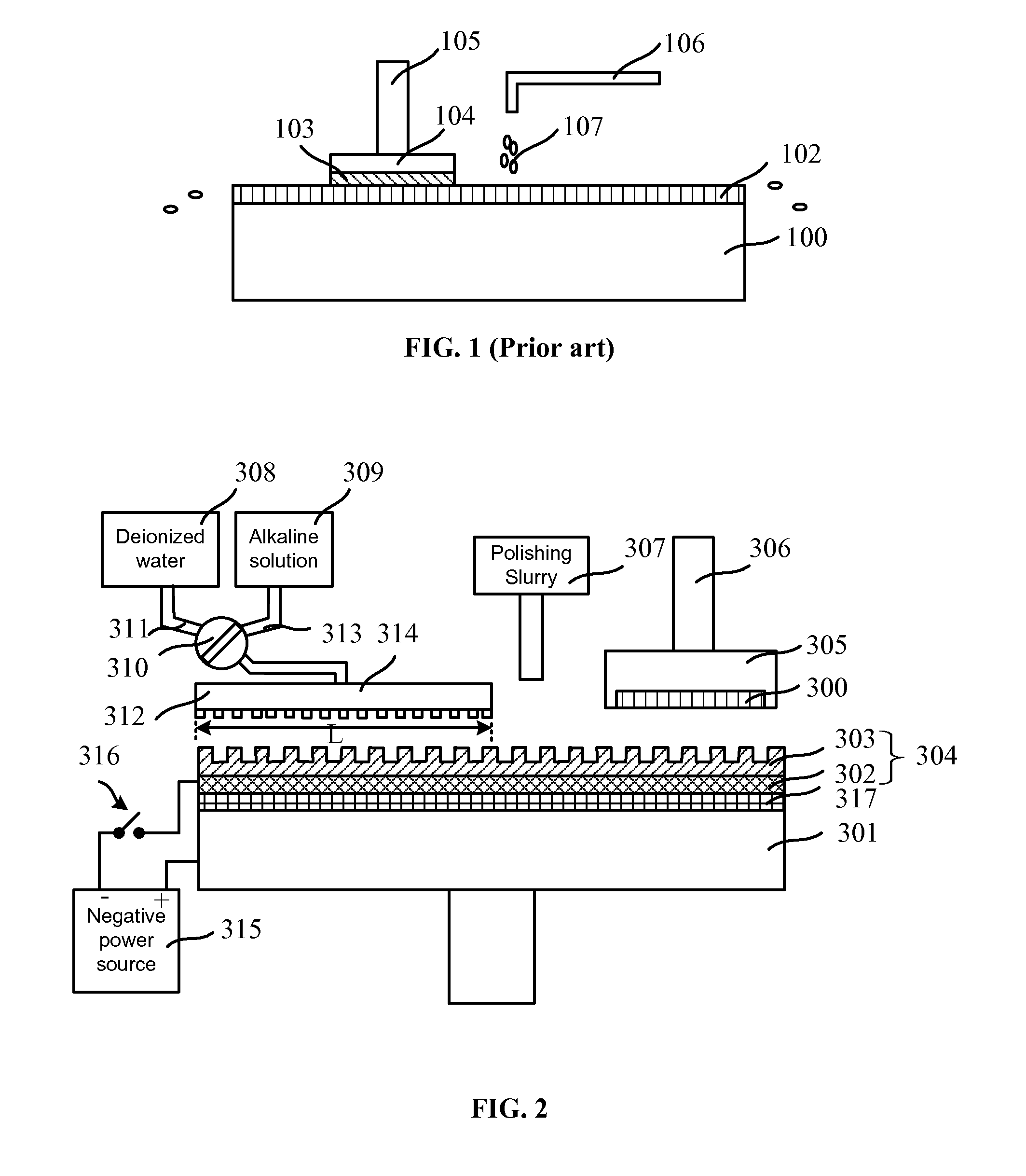
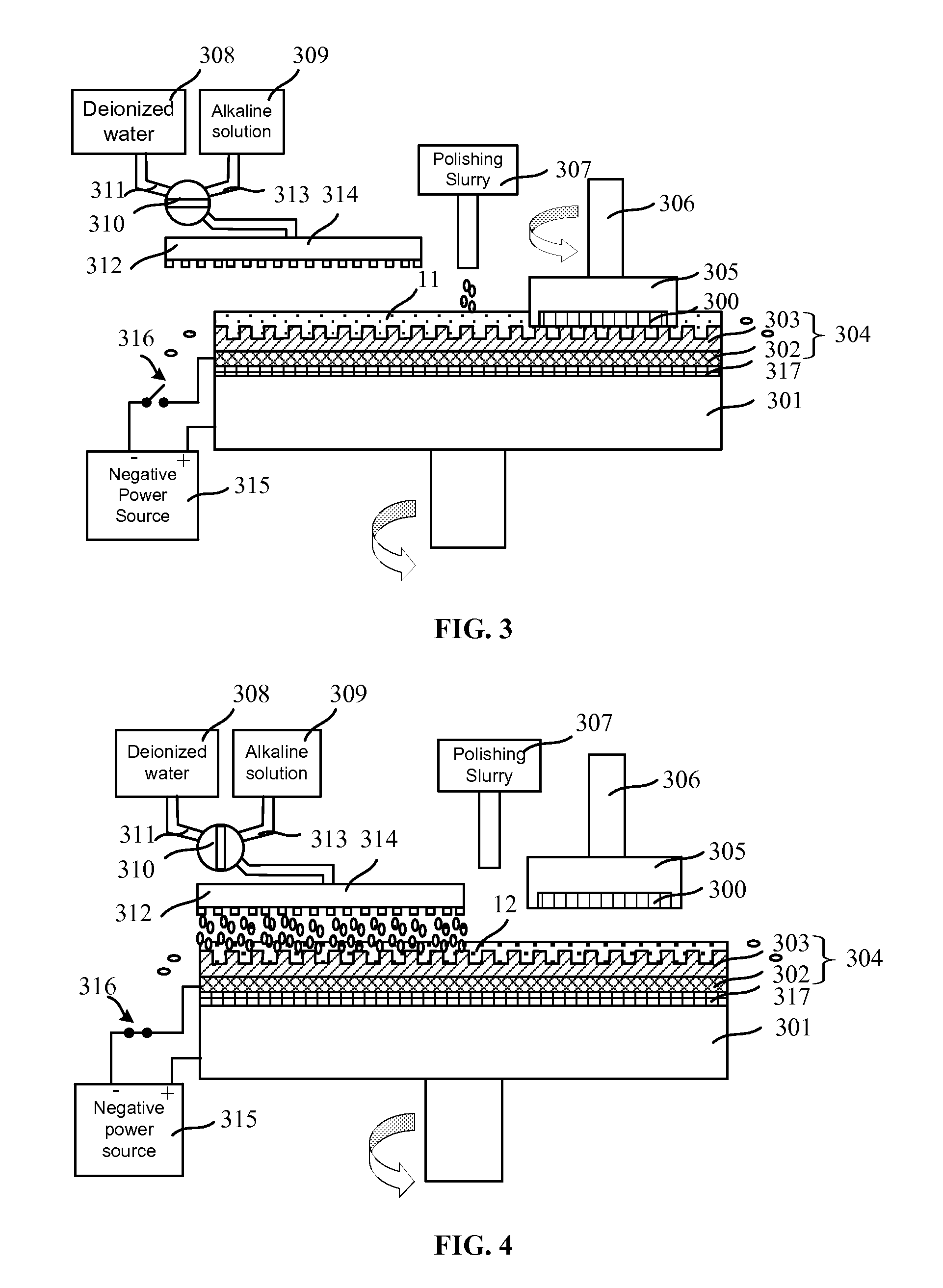
A chemical mechanical planarization (CMP) apparatus is provided. The CMP apparatus includes at least one platen; and a polishing pad disposed on the platen. The CMP apparatus also includes a polishing head disposed above the platen and configured to clamp a to-be-polished wafer; and a basic solution supply port disposed above the platen and configured to supply a basic solution onto a surface of the polishing pad. Further, the CMP apparatus includes a slurry arm disposed above the platen and configured to supply a polish slurry on the surface of the polishing pad; and a deionized water supply port configured to supply deionized water onto the surface of the polishing pad. Further, the CMP apparatus also includes a negative power source configured to apply a negative voltage onto the surface of the polishing pad.

Description

CROSS-REFERENCES TO RELATED APPLICATIONS[0001]This application claims the priority of Chinese patent application No. 201310744276.6, filed on Dec. 30, 2013, the entirety of which is incorporated herein by reference.FIELD OF THE INVENTION[0002]The present invention generally relates to the field of semiconductor manufacturing technology and, more particularly, relates to chemical mechanical planarization apparatus and chemical mechanical planarization methods thereof.BACKGROUND[0003]With the rapid development of ultra large scale integration (ULSI), the fabrication process of integrate circuits (ICs) has become more and more complex; and more and more precise. In order to increase the integration level and lower the production cost, the number of the devices in a unit area has been increasing. Thus, it has been difficult to lay out lines (interconnect structure, etc) in one plane, i.e., two-dimensional layout; and a multiple-layered layout technique has been adapted to utilize the ve...

Claims


Application Information

Patent Timeline
IPC IPC(8): B24B37/04H01L21/306B24B57/02
CPCB24B37/04H01L21/30625B24B57/02B23H3/02B23H7/14B24B37/044B24B37/046B24B37/20B24B37/24B24D3/00H01L21/32115H01L21/3212H01L21/32125H01L21/67051H01L21/6715H05K3/07
Inventor DENG, WUFENG
Owner SEMICONDUCTOR MANUFACTURING INTERNATIONAL (BEIJING) CORP
Why Eureka
Try Eureka