Shock mitigation apparatus

a technology of shock mitigation and apparatus, which is applied in the direction of adjustable chairs, cycle equipments, chairs, etc., can solve the problems of high-performance watercraft, physical injury, and subject passengers to repetitive high g-forces, so as to reduce the amount of shock, prevent excessive movement of the torso and neck, and reduce the likelihood of spinal injuries

Inactive Publication Date: 2015-07-02
ZWAAN PAUL FRANCIS
View PDF8 Cites 7 Cited by
  • Summary
  • Abstract
  • Description
  • Claims
  • Application Information

AI Technical Summary

Benefits of technology

[0024]The shock mitigation apparatus described above confers a number of advantages. A first advantage may be that the apparatus allows for shock mitigation in three axes i.e. three planes of movement and axes of rotation. This may enable an occupant to reduce the amount of shock transmitted to their body from both vertical and lateral impact forces thereby preventing excessive movement of the torso and neck and less likelihood of spinal injuries (unlike coil or air springs that function in only one direction). Secondly, the apparatus is adjustable where the aperture therein the leaf spring allows the leaf spring to be tuned and control the amount of flexure or compliance required depending on occupant and particular application. This overcomes a problem of prior art shock mitigation apparatus where the flexure of the spring is not tuneable. For example, the flexure may be tuned to provide a progressive rate spring or may be to control the stiffness of the spring independently of the three axes where a softer or firmer spring may be manufactured to accommodate sid

Problems solved by technology

High-speed, high performance watercraft, as used in both military and civilian application, subject the passengers to repetitive high G-forces resulting from the sudden deceleration of the watercraft as it falls off waves or hits waves while going at a high forward speed and a high angle of attack.
Such repetitive impacts are both debilitating to the watercraft's occupants, preventing them from carrying out their tasks, and further may result in physical injury.
As above, these effects can cause fatigue and injuries to the boats' passengers and crew especially when subjected to prolonged periods of constant impacts.
Whilst a well designed and built boat can mostly withstand these shocks caused by these impacts, the passengers and crew experience an uncomfortable ride which reduces physical, cognitive and psychomotor performance and increases the risk of acute and chronic musculoskeletal injuries.
At worst, it can result in serious injury or death.
The muscle tissue and organs themselves act as shock absorbers that try to dampen vibration and can become fatigued over time.
As fatigue continues, the potential for declining work performance and even injury increase due to the unpredictable nature of shocks that come from high speed navigation in significant waves.
However, a disadvantage of U.S. Pat. No. 5,810,125 is that to mitigate shock, the system requires the use of an array of components such as complex electronic controllers, sensor units, electroh

Method used


Image

  • Shock mitigation apparatus
  • Shock mitigation apparatus
  • Shock mitigation apparatus

Examples


working examples

[0105]The above described shock mitigation apparatus and uses are now described by reference to specific embodiments and examples.

example 1

Non Height Adjustable Dual Leaf Spring

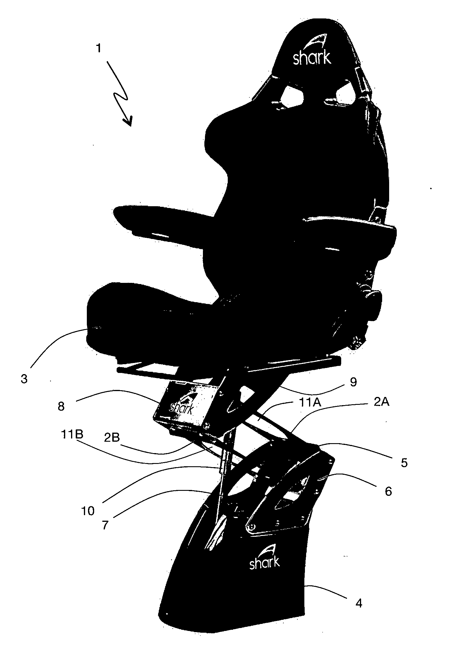
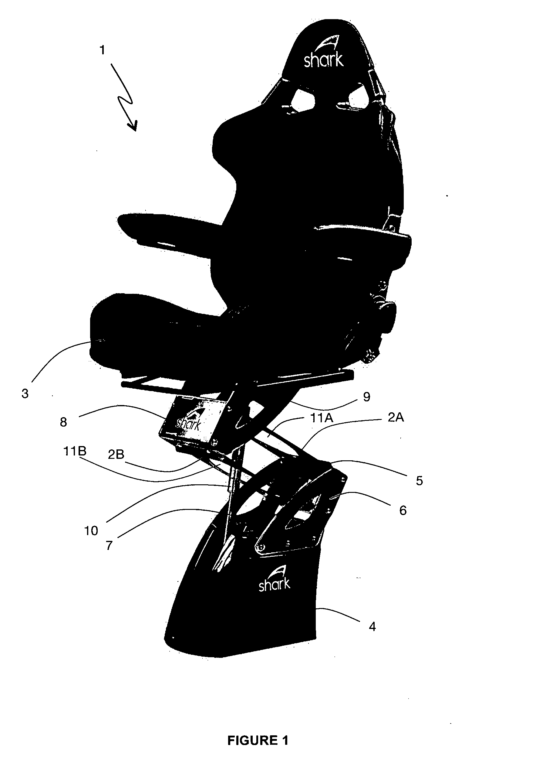
[0106]Referring to FIG. 1, an assembled shock mitigation apparatus 1 with dual leaf springs 2A,B and a seat member 3 in the form of captain's chair design is illustrated. A base assembly in the form of a plinth 4 is used to support the seat member 3 and is attached to the sole of a boat (not shown) with fasteners and reinforcing plates / washers (not shown) in known fashion. A lower clamp member 5 is securely mounted to a pair of side support members 6 attached to the base assembly 4. An access port 7 is secured to the top of the plinth 4. A top and bottom leaf spring 2A,B slidingly engages with the lower clamp member 5. In the same way, an upper clamp member 8 is securely mounted to a pair of side support members 9, attached to a bottom assembly of the seat member 3. The lower and upper clamp members 5,8 are linked together via the top and bottom leaf springs 2A,B which are slidingly engaged and secured to the upper and lower clamp members 5,8 wi...

example 2

Non Height Adjustable Dual Leaf Spring in Use

[0119]Referring to FIG. 8, a simplified schematic diagram shows an applied load on a dual spring assembly mitigation apparatus 1 of FIG. 1 in use. The seat member, side mounting plates and plinth are not shown for clarity. The springs 2A,B are clamped at each end of the clamping members 5,8 where the lower clamp member 5 maintains one end of the springs 2A,B at a fixed angle relative to the side support members (not shown) and plinth (not shown). The upper clamp member 8 also maintains the distal end of the springs 2A,B at a fixed angle relative to the side support members and seat assembly. As can be seen, once a vertical load force is applied downwards to the shock mitigation apparatus 1, a deflection in the springs 2A,B in the form of an S-shaped curve is imparted thereby absorbing the vertical load force.


PUM


Abstract

Described herein is a shock mitigation apparatus. More specifically, a shock mitigation apparatus which relates to a new and improved seating system, such as may be utilised in a marine environment, able to absorb shocks transmitted to the seat system from a structure to which the seat is affixed. The shock mitigation apparatus includes a tuneable spring to alter and/or control flexure within the spring in three planes of movement (longitudinal surge, vertical heave and lateral sway) and axes of rotation (roll, pitch and yaw) depending on occupant and/or particular application.

Description

RELATED APPLICATIONS[0001]This application is a 35 U.S.C. §371 National Stage Application of International Application No. PCT / NZ2013 / 000117, filed Jul. 4, 2013, which derives priority from New Zealand patent application number 601068, filed Jul. 4, 2012, both of which are incorporated herein by reference.TECHNICAL FIELD[0002]Described herein is a shock mitigation apparatus. More specifically, a shock mitigation apparatus which relates to a new and improved seating system, such as may be utilised in a marine environment, able to absorb shocks transmitted to the seat system from a structure to which the seat is affixed. The shock mitigation apparatus includes a tuneable spring to alter and / or control flexure within the spring in three planes of movement (longitudinal surge, vertical heave and lateral sway) and axes of rotation (roll, pitch and yaw) depending on occupant and / or particular application.BACKGROUND ART[0003]High-speed, high performance watercraft, as used in both military...

Claims


Application Information

Patent Timeline
IPC IPC(8): B63B29/04F16F1/02F16F1/22F16F3/02A47C3/20A47C7/02
CPCB63B29/04A47C3/20A47C7/025B63B2029/043F16F3/02F16F1/021F16F1/22A47C15/004B60N2/502B60N2/505B60N2/507B60N2/525B60N2/546
Inventor ZWAAN, PAUL FRANCIS
Owner ZWAAN PAUL FRANCIS
Why Eureka
Try Eureka