Machine body and machinery

a technology of machine body and machine body, applied in the direction of machines/engines, mechanical equipment, transportation and packaging, etc., can solve the problems of easy heat in the engine room, easy temperature rise, and concern about performance degradation, so as to prevent excessive cooling, reduce energy consumption of cooling fans, and easy to fill the room with heat

Inactive Publication Date: 2015-07-02
CATEPILLAR SARL
View PDF2 Cites 7 Cited by
  • Summary
  • Abstract
  • Description
  • Claims
  • Application Information

AI Technical Summary

Benefits of technology

[0015]According to the invention of claim 1, since the cooling fan is installed in the vicinity of the reducing agent injector that injects the liquid reducing agent supplied from the reducing agent supplier so as to face the reducing agent injector, and the cooling wind of the external air taken in from the outside of the machine room is blown against the reducing agent injector, the reducing agent injector can be directly cooled by the external air to prevent a concern that the liquid reducing agent may be thermally decomposed in the reducing agent injector.
[0016]According to the invention of claim 2, since the control device controls the cooling fan according to the temperature of the reducing agent injector or its vicinity detected by the temperature detecting device, suitable temperature management of the reducing agent injector is enabled while suppressing the energy consumption for cooling the cooling fan. As a result, the injection of the reducing agent injector at an optimal temperature is enabled.
[0017]According to the invention of claim 3, since the closing cover is enabled to be installed in the cooling fan installation place instead of the detached cooling fan, it is possible to cope with a concern that the liquid reducing agent may freeze under a low-temperature environment, and excessive cooling can be prevented.
[0018]According to the invention of claim 4, in the machinery that does stationary work or low-speed movement work, the machine room is easily filled with heat and the temperature of the machine room becomes high easily, and thus, there is a great effect that the reducing agent injector can be directly cooled by the cooling fan to prevent the liquid reducing agent from being thermally decomposed in the reducing agent injector.

Problems solved by technology

However, in machineries that perform stationary work, such as a hydraulic shovel, an engine room is easily filled with heat, and the temperature of the engine room becomes high easily.
When the reducing agent tank is arranged in a place like machine rooms, such as an engine room, of which the temperature becomes extremely high, the thermal decomposition temperature of the urea water is approached and consequently, there is a concern about degradation of performance.
If the reducing agent supplied to a fuel injection device is not managed at a suitable temperature, there is a concern that the liquid reducing agent may reach its thermal decomposition temperature before being injected into the exhaust gas treatment device.

Method used


Image

  • Machine body and machinery
  • Machine body and machinery
  • Machine body and machinery

Examples


Embodiment Construction

[0028]Hereinafter, the invention will be described in detail on the basis of an embodiment illustrated in FIGS. 1 to 5 and another embodiment illustrated in FIGS. 6 to 9.

[0029]First, the embodiment illustrated in FIGS. 1 to 5 will be described.

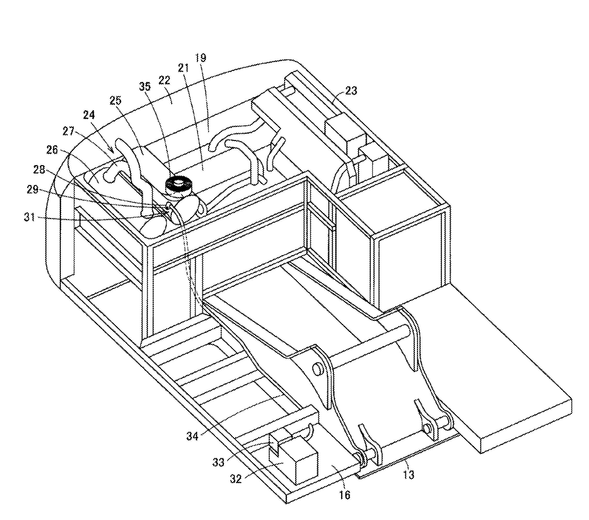
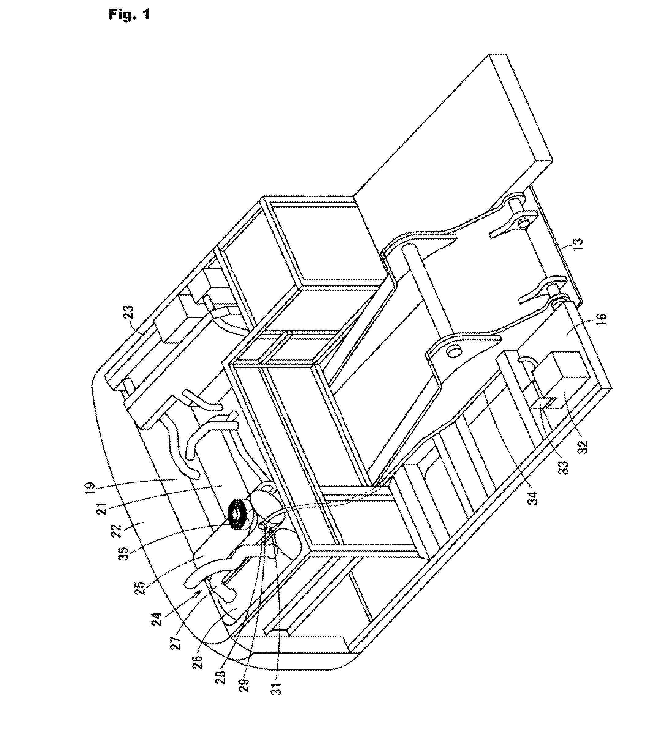
[0030]As illustrated in FIG. 4, in a hydraulic shovel type machinery 10, a machine body 11 includes a lower traveling body 12, and an upper swivel body 13 that is provided in a swivelable manner at the lower traveling body 12, and a bucket type working device 14 is mounted on the upper swivel body 13 of the machine body 11.

[0031]A cab 15 where an operator's seat is provided, and a storage box 16 that houses tools or the like are provided via the working device 14 on the upper swivel body 13. A fuel tank 17 and a hydraulic oil tank 18 are provided behind the storage box 16. An engine 21 is installed in a machine room 19 (engine room) within the machine body 11 located further rearward than a swiveling bearing portion of the upper swivel body 13...


PUM


Abstract

Provided is a machine body capable of preventing thermal decomposition of a liquid reducing agent in a reducing agent injector. The machine body includes an exhaust gas treatment device that reduces nitrogen oxides in exhaust gas of an engine provided within a machine room, and a reducing agent supplier that supplies the liquid reducing agent to the exhaust gas treatment device. The exhaust gas treatment device includes a reducing agent injector that injects the liquid reducing agent supplied from the reducing agent supplier, and a cooling fan that is installed in the vicinity of the reducing agent injector so as to face the reducing agent injector. The cooling fan performs cooling by blowing cooling wind of external air, which is taken in from the outside of the engine room, against the reducing agent injector and its upstream side.

Description

CROSS-REFERENCE TO RELATED APPLICATIONS[0001]This application is a National Stage of International Patent Application No. PCT / JP2013 / 063250, filed May 13, 2013, which claims priority to foreign Japanese Patent Application No. 2012-116877, filed May 22, 2012, the contents of which are incorporated herein by reference in their entirety.TECHNICAL FIELD[0002]The present invention relates to a machine body including an exhaust gas treatment device using a liquid reducing agent, and a working machine including the machine body.BACKGROUND ART[0003]Although urea water is used as a liquid reducing agent for reducing nitrogen oxides in exhaust gas of an internal combustion engine, when the thermal decomposition temperature of this urea water is about 150° C. and the freezing temperature of the urea water is −11° C. in a urea concentration of 32.5% (trade name: AdBlue), in the related art, this urea water is often arranged in the vicinity of a heat source so as to warm a reducing agent tank fo...

Claims


Application Information

Patent Timeline
Patent Type & Authority Applications(United States)
IPC IPC(8): E02F9/08F01N3/035
CPCE02F9/0866F01N3/035E02F9/0883E02F9/18F01N3/2066F01N2260/022F01N2610/02F01N2610/11F01N2590/08Y02A50/20Y02T10/12F01N3/08F01N3/24F01N3/36E02F9/00
Inventor IMANO, TORUNAKAI, AKITONISHIYAMA, SHINICHI
Owner CATEPILLAR SARL
Why Eureka
Try Eureka