
Display panel, display apparatus having the same and method of manufacturing the same

a display panel and display panel technology, applied in the direction of electrical devices, instruments, semiconductor devices, etc., can solve the problems of size, portability, electrical characteristic of the display panel, etc., and achieve the effect of improving the electrical contact characteristi

Active Publication Date: 2015-07-02
SAMSUNG DISPLAY CO LTD
View PDF6 Cites 29 Cited by
  • Summary
  • Abstract
  • Description
  • Claims
  • Application Information

AI Technical Summary

Benefits of technology

The patent is about a display panel that improves how well a driving chip and output pads are connected. The panel has a specific arrangement of output pads made with a resin that helps the contact between the chip and pads. This results in a better display and better electrical contact.

Problems solved by technology

However the CRT display apparatus has a weakness with a size or portability.
When the driving chip is being mounted on the display panel, a resin of an anisotropic conductive film may not flow sufficiently, so that a falling of an electrical characteristic may be caused.

Method used


Image

  • Display panel, display apparatus having the same and method of manufacturing the same
  • Display panel, display apparatus having the same and method of manufacturing the same
  • Display panel, display apparatus having the same and method of manufacturing the same

Examples


Embodiment Construction

[0046]Hereinafter, the inventive concept will be explained in detail with reference to the accompanying drawings.

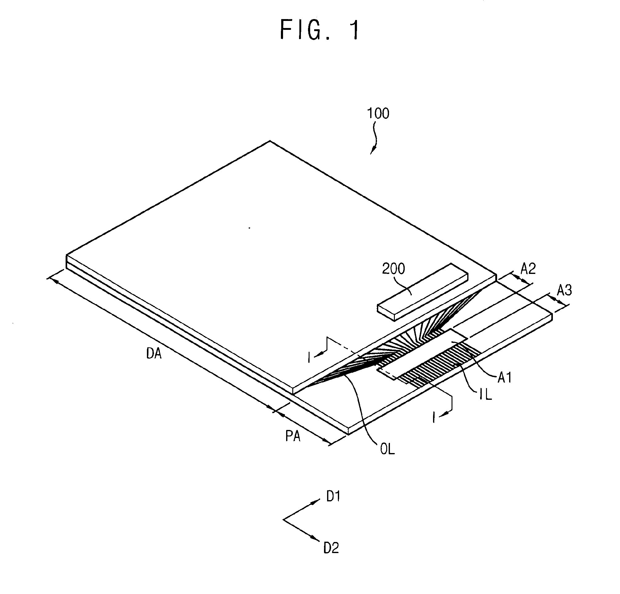
[0047]FIG. 1 is a perspective view illustrating a display panel according to an example embodiment of the inventive concept.

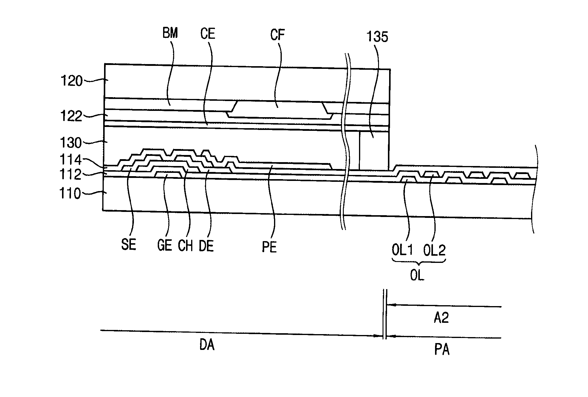
[0048]Referring to FIG. 1, a display panel 100 includes a display area DA and a peripheral area PA.

[0049]An image is displayed on the display area DA. A circuit wiring to display the image is formed in the display area DA. The peripheral area PA is adjacent to the display area DA in a first direction D1. The peripheral area PA includes a pad area A1, an output fan-out area A2 and an input area A3.

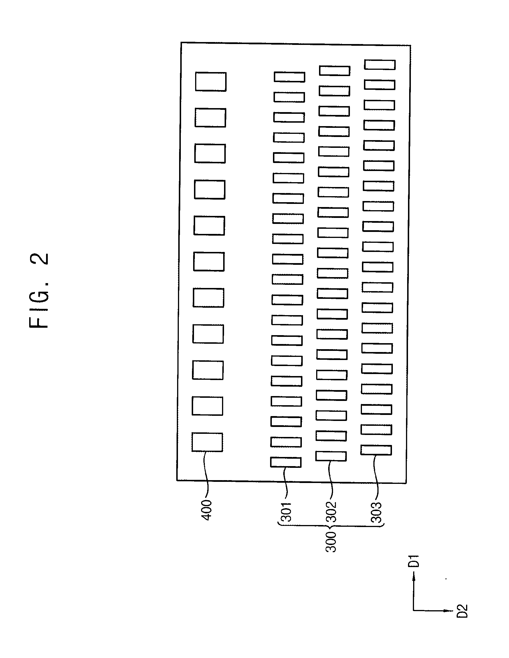
[0050]The pad area A1 is spaced apart from the display area DA, and extends in a second direction D2 which is substantially perpendicular to the first direction D1. A plurality of output pads and a plurality of input pads are disposed in the pad area A1. The output pads and the input pads are electrically connected to a driving chip 200. (refers to FIG. 2).

[...


PUM


Abstract

A display panel includes a display area configured to display an image, and a peripheral area adjacent to the display area. The peripheral area includes a pad area in which a plurality of output pads are disposed. The output pads are arranged in a matrix formed having M row*N column (M and N are normal numbers, M is 3 or larger than 3). Each of the output pads has a center of the output pad spaced apart from a center of an adjacent output pad by a distance D in a first direction. Each of the output pads is spaced apart from an adjacent output pad by a gap. Each of the output pads has a center of the output pad spaced apart from a center of an adjacent output pad by a pitch P in a second direction which is substantially perpendicular to the first direction. An equation “P<D / (M−1)” is satisfied.

Description

[0001]This application claims priority under 35 U.S.C. §119 to Korean Patent Application No. 10-2014-0000327, filed on Jan. 2, 2014, the disclosure of which is incorporated by reference herein in its entirety.BACKGROUND[0002]1. Field[0003]Exemplary embodiments of the inventive concept relate to a display panel, a display apparatus including the display panel, and a method of manufacturing the display panel.[0004]More particularly, exemplary embodiments of the inventive concept relate to a display panel for a liquid crystal display apparatus, a display apparatus including the display panel, and a method of manufacturing the display panel.[0005]2. Description of the Related Art[0006]Recently, a display apparatus having light weight and small size has been manufactured. A cathode ray tube (CRT) display apparatus has been used due to a performance and a competitive price. However the CRT display apparatus has a weakness with a size or portability. Therefore the liquid crystal display ap...

Claims


Application Information

Patent Timeline
IPC IPC(8): H01L27/12
CPCH01L27/124H01L27/1259H01L27/1225G02F1/13452G02F1/13458G02F1/133512G02F1/133514G02F1/136227G02F1/136286G02F1/1368G02F1/136295
Inventor MOH, SANG-MOONKIM, LUCK-HYUN
Owner SAMSUNG DISPLAY CO LTD
Learn More