Robust direct injection fuel pump system

a fuel pump and direct injection technology, applied in the direction of fuel injection apparatus, charge feed system, electric control, etc., can solve the problems of increasing nvh and degradation of the di fuel pump, accelerating pump degradation, and lubricating the di fuel pump may not be maintained, so as to improve engine performance, increase torque and fuel economy, and reduce vehicle emissions. , wear and tear

Active Publication Date: 2015-07-16
FORD GLOBAL TECH LLC
View PDF7 Cites 13 Cited by
  • Summary
  • Abstract
  • Description
  • Claims
  • Application Information

AI Technical Summary

Benefits of technology

[0001]Port fuel direct injection (PFDI) engines are capable of advantageously utilizing both port injection and direct injection of fuel. For example, at higher engine loads, fuel may be injected into the engine using direct fuel injection, thereby improving engine performance (e.g., increasing available torque and fuel economy). At lower engine loads, fuel may be injected into the engine using port fuel injection, thereby reducing vehicle emissions, NVH, and wear of the direct injection system components, (e.g., injectors, DI pump solenoid valve, and the like). In PFDI engines, the low pressure fuel pump supplies fuel from the fuel tank to both the port fuel injectors and the direct injection fuel pump. Because there may be periods of engine operation during which the direct injection fuel pump may not be running (e.g., during port fuel injection at low engine loads), lubrication of the DI fuel pump may not be maintained and wear, NVH and degradation of the DI fuel pump may be increased.

Problems solved by technology

Because there may be periods of engine operation during which the direct injection fuel pump may not be running (e.g., during port fuel injection at low engine loads), lubrication of the DI fuel pump may not be maintained and wear, NVH and degradation of the DI fuel pump may be increased.
First, because the direct injection fuel pump may not be used at low and idle engine loads in PFDI engines, pump lubrication may be reduced, thereby accelerating pump degradation.
Furthermore, operating the direct injection pump during engine idle conditions can result in excessive NVH due to ticks generated by the DI fuel pump and due to a lack of engine noise to mask the pump noise.
Second, conventional methods of controlling the low pressure fuel pump expend excessive pump power, thereby reducing fuel economy and pump durability, or do not robustly deliver fuel to the direct injection fuel pump, thereby causing pump cavitation, which may reduce engine performance and aggravate injection pump degradation.

Method used


Image

  • Robust direct injection fuel pump system
  • Robust direct injection fuel pump system
  • Robust direct injection fuel pump system

Examples


Embodiment Construction

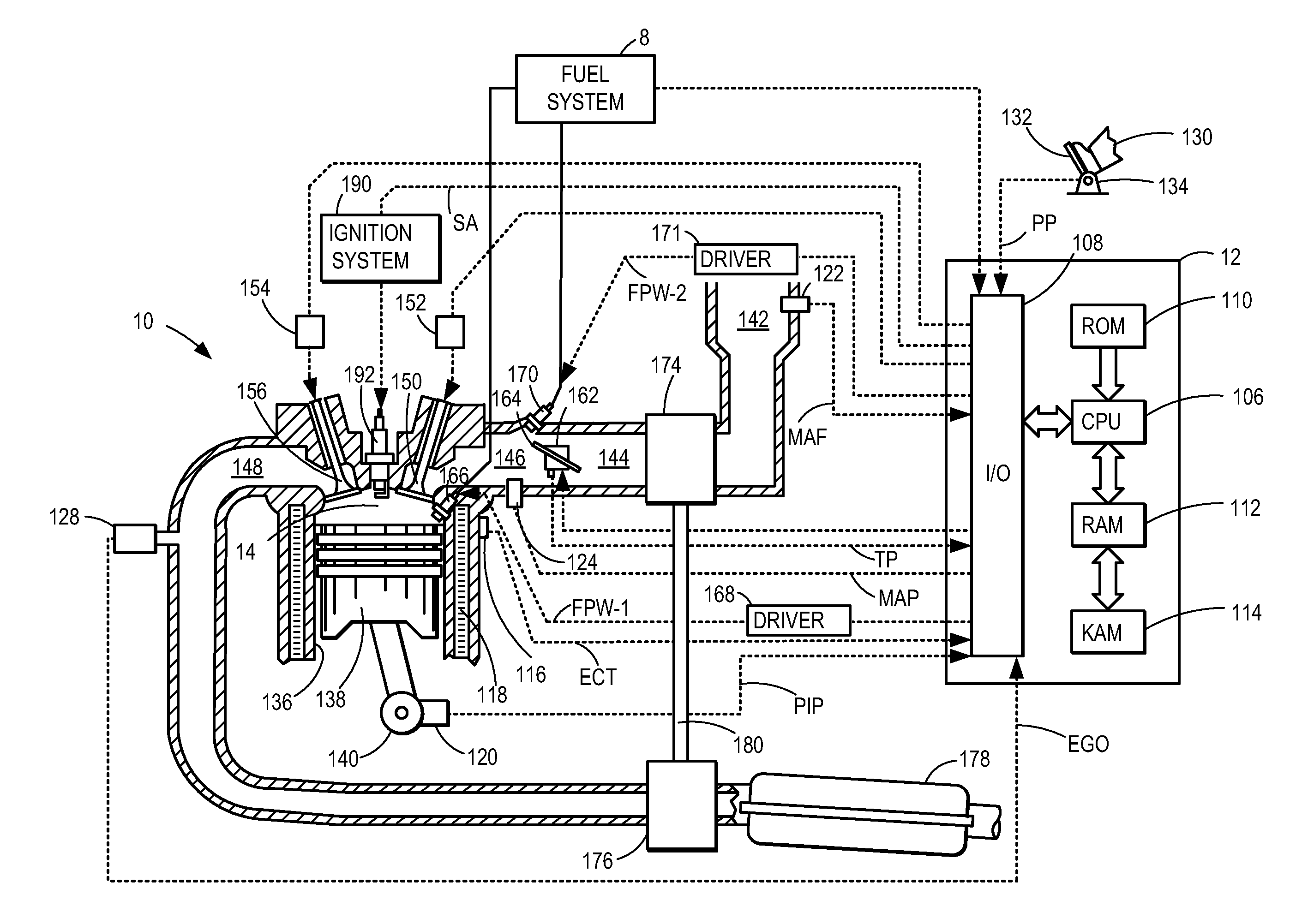
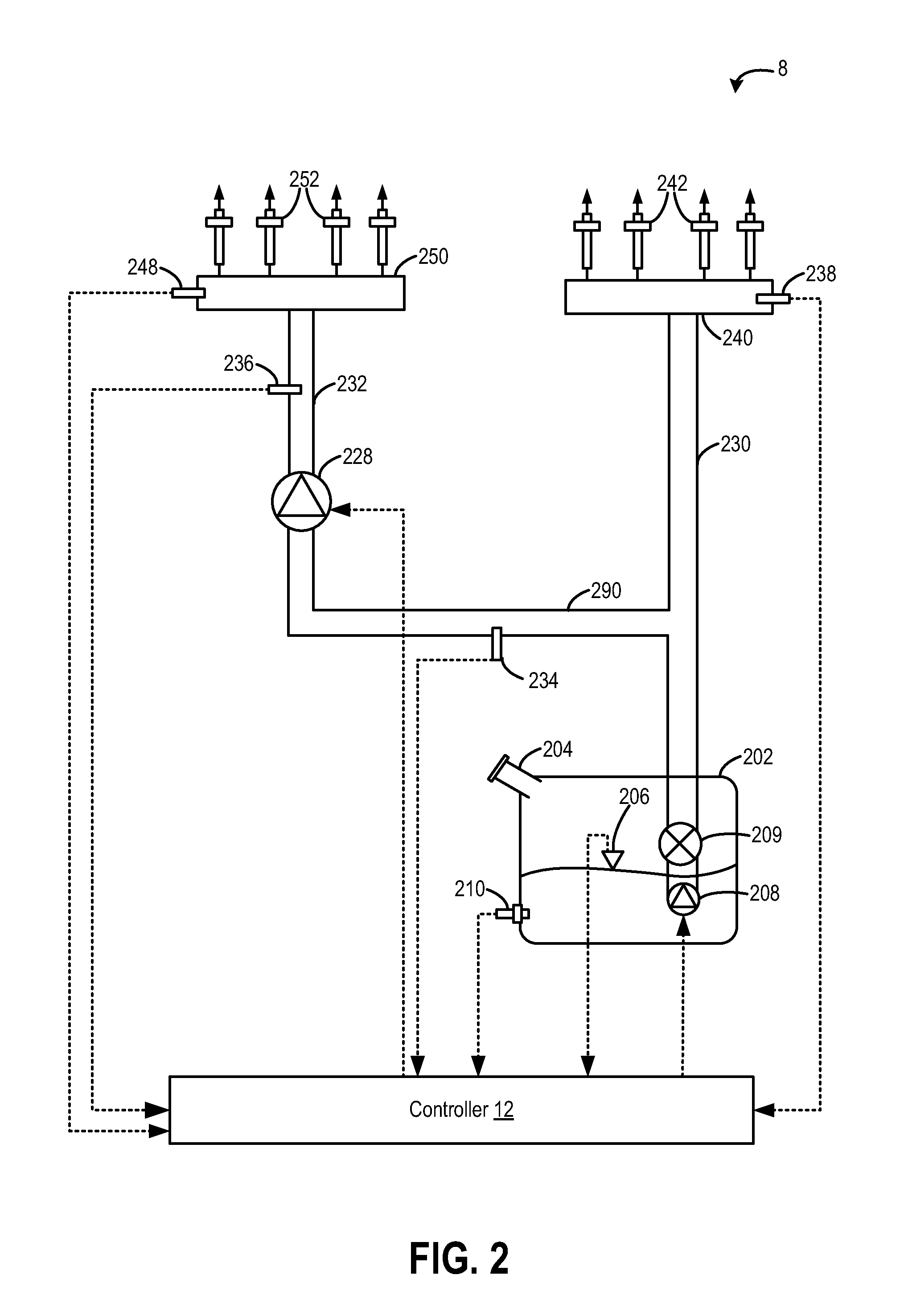
[0017]The following disclosure relates to methods and systems for operating a port fuel direct injection (PFDI) engine, such as the engine system of FIG. 1. The fuel system of a PFDI engine, as illustrated in FIG. 2, may be configured to deliver one or more different fuel types to an internal combustion engine, such as the engine of FIG. 1. A direct injection fuel pump as shown in FIG. 4 may be incorporated into the systems of FIGS. 1 and 2. The port fuel direct injection engine may operate as shown in FIGS. 3B and 6 according to a method as illustrated in FIG. 5. FIG. 3A is an example plot illustrating pressure in a fuel passage pressure and fuel volume in the fuel passage. FIG. 7 is an example plot of DI fuel pump duty cycle versus DI fuel rail pressure.

[0018]Turning to FIG. 1, it depicts an example of a combustion chamber or cylinder of internal combustion engine 10. Engine 10 may be controlled at least partially by a control system including controller 12 and by input from a veh...


PUM


Abstract

A method for a PFDI engine may comprise, during a first condition, comprising direct-injecting fuel to the PFDI engine, estimating a fuel vapor pressure, and setting a fuel lift pump pressure greater than the fuel vapor pressure by a threshold pressure difference, and during a second condition, comprising port-fuel-injecting fuel to the PFDI engine, setting a DI fuel pump command signal greater than a threshold DI fuel pump command signal without supplying fuel to a DI fuel rail.

Description

BACKGROUND AND SUMMARY[0001]Port fuel direct injection (PFDI) engines are capable of advantageously utilizing both port injection and direct injection of fuel. For example, at higher engine loads, fuel may be injected into the engine using direct fuel injection, thereby improving engine performance (e.g., increasing available torque and fuel economy). At lower engine loads, fuel may be injected into the engine using port fuel injection, thereby reducing vehicle emissions, NVH, and wear of the direct injection system components, (e.g., injectors, DI pump solenoid valve, and the like). In PFDI engines, the low pressure fuel pump supplies fuel from the fuel tank to both the port fuel injectors and the direct injection fuel pump. Because there may be periods of engine operation during which the direct injection fuel pump may not be running (e.g., during port fuel injection at low engine loads), lubrication of the DI fuel pump may not be maintained and wear, NVH and degradation of the DI...

Claims


Application Information

Patent Timeline
Patent Type & Authority Applications(United States)
IPC IPC(8): F02B17/00
CPCF02B17/005F02D41/3845F02D41/3094F02D41/3854F02D2041/3881F02D2041/389F02D2250/02F02M63/029
Inventor SURNILLA, GOPICHANDRAPURSIFULL, ROSS DYKSTRAMEINHART, MARKBASMAJI, JOSEPH F.
Owner FORD GLOBAL TECH LLC
Why Eureka
Try Eureka