Dielectric resonator antenna

a dielectric resonator and antenna technology, applied in the field of substrate buried dielectric resonator antennas, can solve the problems of deceasing antenna gain, deteriorating antenna characteristics, and reducing the radiation efficiency of antennas, so as to reduce process costs

Inactive Publication Date: 2015-07-23
ELECTRONICS & TELECOMM RES INST
View PDF10 Cites 39 Cited by
  • Summary
  • Abstract
  • Description
  • Claims
  • Application Information

AI Technical Summary

Benefits of technology

[0028]According to the dielectric resonator antenna of the present invention, the dielectric resonator is buried inside the substrates to remove a metal pattern exposed to the outside, thereby removing an expensive gold plating process for protecting the metal pattern and thus decreasing process cost.

Problems solved by technology

However, when the patch antenna operated in a millimeter wave frequency band, particularly, a high frequency band of about 60 GHz or higher, is manufactured, there is a problem in that an antenna characteristic deteriorates due to leakage of a signal by generation of a surface wave propagation throughout a surface of a dielectric substrate.
This leakage of the signal degrades radiation efficiency of an antenna, and antenna gain also deceases due to this leakage.
In the meantime, a process of forming the air cavity, which digs out an inner side of the substrate in the LTCC process, degrades a yield of a product, so that the process is not appropriate to mass production.
As described above, the existing dielectric resonator antenna using the LTCC requires an expensive gold plating process due to the metal exposed to the outside, so that there is a problem in that a manufacturing process is considerably increased.

Method used


Image

  • Dielectric resonator antenna
  • Dielectric resonator antenna
  • Dielectric resonator antenna

Examples


Embodiment Construction

[0039]Hereinafter, an embodiment of the present invention will be described with reference to the accompanying drawings in detail. However, the present invention is not limited to an embodiment disclosed below and may be implemented in various forms and the scope of the present invention is not limited to the following embodiments. Rather, the embodiment is provided to more sincerely and fully disclose the present invention and to completely transfer the spirit of the present invention to those skilled in the art to which the present invention pertains, and the scope of the present invention should be understood by the claims of the present invention.

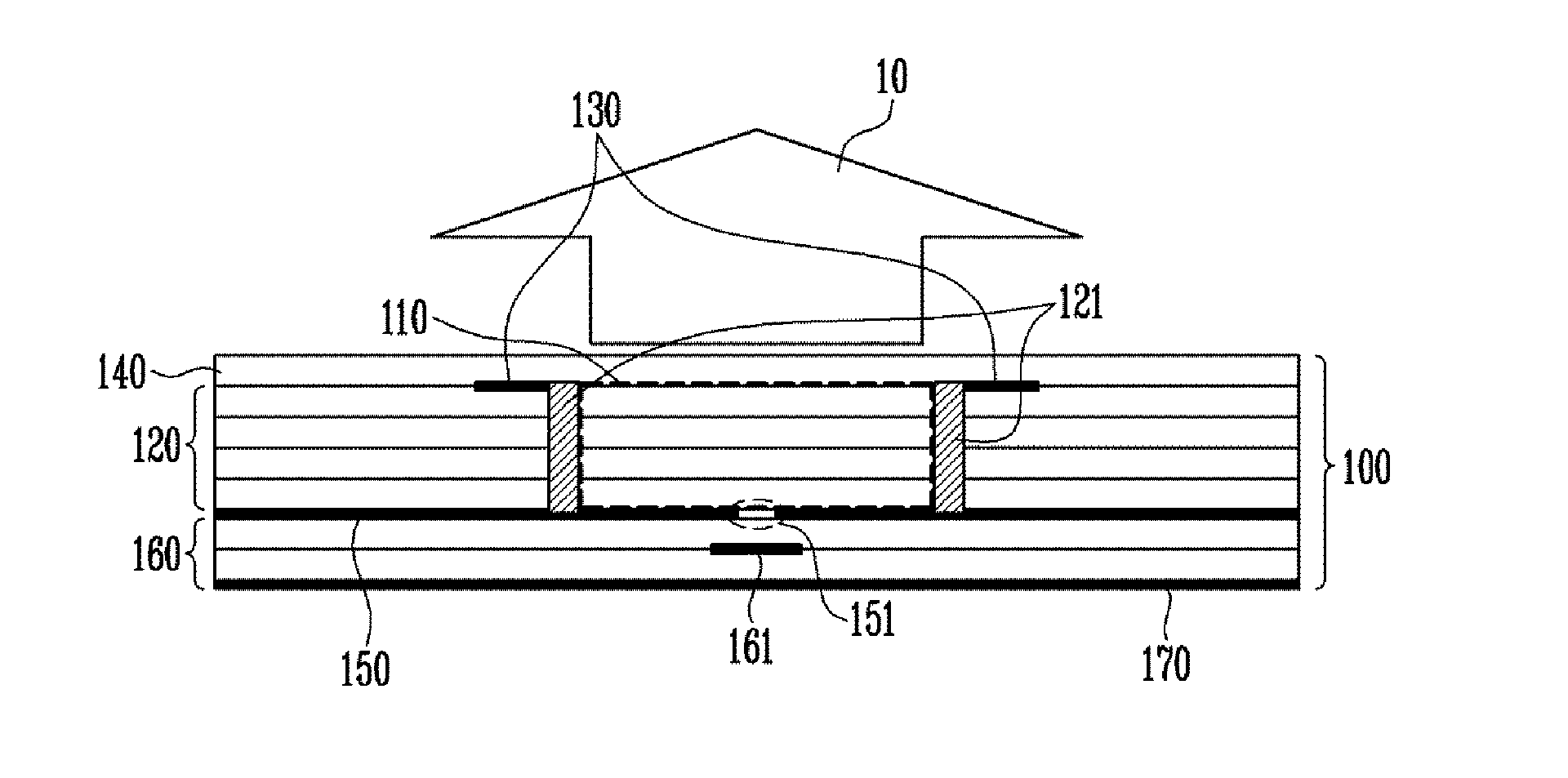
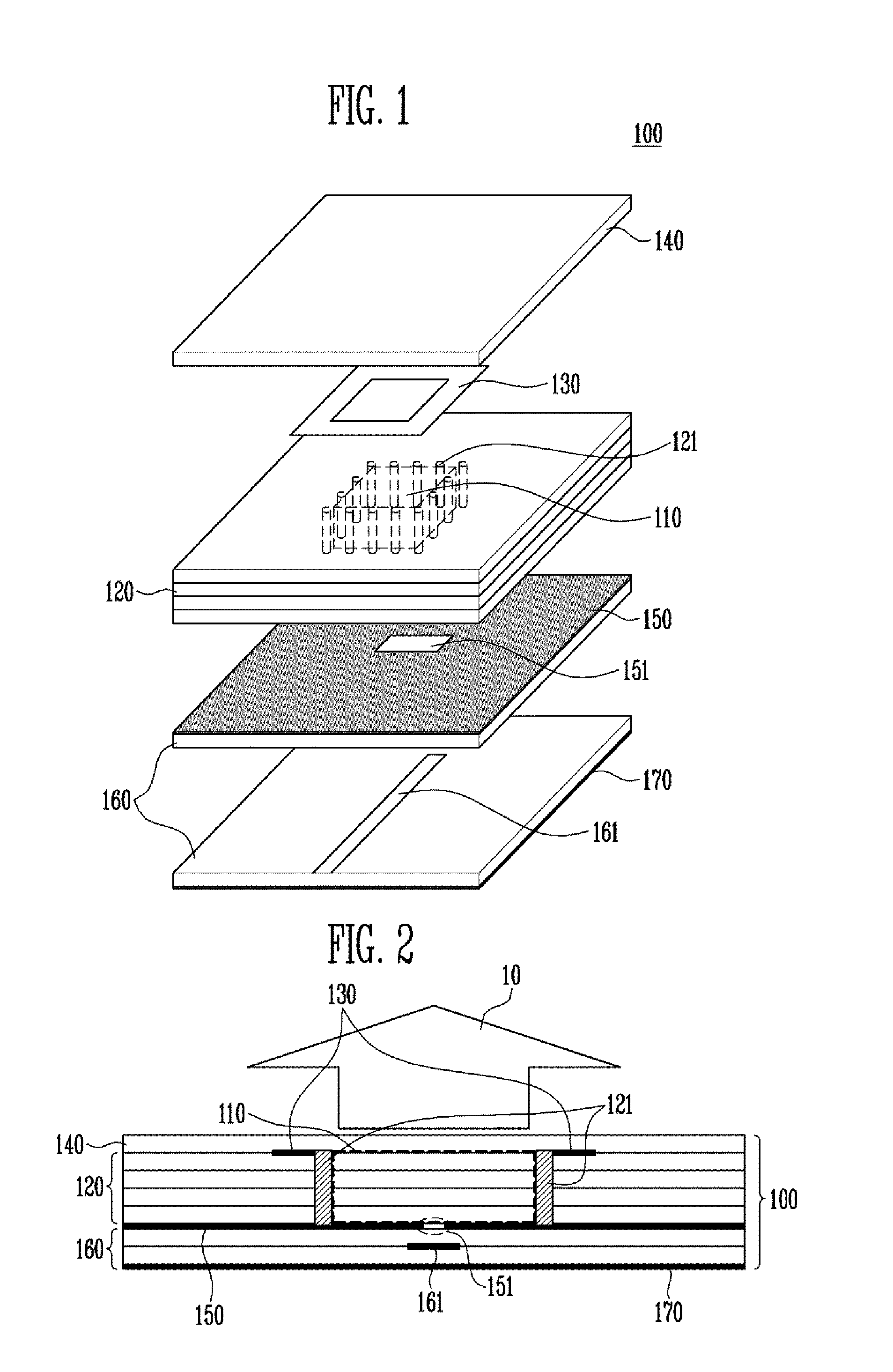
[0040]The present invention provides a dielectric resonator antenna, in which a metal pattern is buried inside substrates in an antenna formed of a plurality of layers to decrease a size of a module. To this end, the present invention will be described based on an antenna, which is implemented by using a multilayer structure Low Tempera...


PUM


Abstract

Disclosed is a dielectric resonator antenna. The dielectric resonator antenna includes: a dielectric resonator; an antenna layer formed inside the dielectric resonator, and including a plurality of vias positioned at a surrounding area of the dielectric resonator; a metal pattern forming an opened surface in an upper portion of the antenna layer; a dielectric layer configured to cover the metal pattern on the dielectric resonator; an internal ground pattern including a coupling aperture for inputting a signal into the dielectric resonator under the dielectric resonator; and a feeding layer including a strip transmission line for transmitting a signal to the dielectric resonator, and positioned under the antenna layer.

Description

CROSS-REFERENCE TO RELATED APPLICATION[0001]This application is based on and claims priority from Korean Patent Application No. 10-2014-0007748, filed on Jan. 22, 2014, with the Korean Intellectual Property Office, the disclosure of which is incorporated herein in its entirety by reference.BACKGROUND[0002]1. Field[0003]The present invention relates to an antenna system, and more particularly, to a substrate buried dielectric resonator antenna based on Low Temperature Co-Fired Ceramic (LTCC), which can decrease manufacturing cost.[0004]2. Discussion of Related Art[0005]A frequency in a millimeter wave band has an excellent straightforward propagation, and a broadband characteristic, compared to a frequency in a microwave band, thereby attracting attentions for application to a radar or communication service. Particularly, since the millimeter wave band has a short wavelength, an antenna is easily miniaturized, thereby innovatively decreasing a size of a system. Broadband communicatio...

Claims


Application Information

Patent Timeline
Patent Type & Authority Applications(United States)
IPC IPC(8): H01Q9/04H01Q1/50H01Q1/48
CPCH01Q9/0485H01Q1/50H01Q1/48
Inventor KIM, DONG YOUNGLIM, JONG WONKIM, CHEON SOO
Owner ELECTRONICS & TELECOMM RES INST
Why Eureka
Try Eureka