Waterproof control unit and method of assembling the same

a technology of waterproof control unit and assembling method, which is applied in the direction of transportation and packaging, electrical apparatus casing/cabinet/drawer, other domestic objects, etc., can solve the problems of convexoconcave sealing surface system drawback, apparent thickness dimension between sealing surfaces becoming larger, etc., and achieve the effect of simplifying the structure of the di

Active Publication Date: 2015-07-30
MITSUBISHI ELECTRIC CORP
View PDF3 Cites 10 Cited by
  • Summary
  • Abstract
  • Description
  • Claims
  • Application Information

AI Technical Summary

Benefits of technology

[0022]It is a first object of the present invention to solve the above-mentioned problems, and to provide a waterproof control unit capable of simplifying the structure of a die for a cover or a base to be subjected to forming or sheet metal working and suppressing a situation where a connector housing has a long body dimension. It is a second object of the present invention to provide a method of assembling a waterproof control unit, which is suited to a waterproof control unit capable of suppressing a situation where a connector housing has a long body dimension.
[0052]Thus, there are effects in that the structure of the die for the cover or the base to be subjected to forming or sheet metal working can be simplified, and that the situation where the connector housing has a long body dimension can be suppressed while reducing the load on the die, thereby being capable of reducing the electric resistance of the contact terminals. Further, as compared to the waterproof control unit in which two sets of convexoconcave sealing surfaces for the cover and the base are provided to the connector housing, the entire width of the sealing surfaces is suppressed by forming the cover and the base through use of the slope portions, the outer-step flat portions, and the inner-step flat portions in a unified manner, or by forming the cover and the base through use of one set of convexoconcave sealing surfaces and the slope portions, the outer-step flat portions, and the inner-step flat portions in combination. Thus, there is an effect in that sealing performance as high as that of the waterproof control unit using two sets of convexoconcave sealing surfaces can be obtained.
[0053]Note that, also when one set of convexoconcave sealing surfaces and the slope portions, the outer-step flat portions, and the inner-step flat portions are used in combination, the width of the convexoconcave sealing surfaces is increased and the fitting depth is decreased as compared to the case where two sets of convexoconcave sealing surfaces are provided. Thus, there is an effect in that the structure of the die can be simplified. Further, there are effects in that the sealing path can be extended by the slope portions, the outer-step flat portions, and the inner-step flat portions as compared to a horizontal surface, and that the strength of the cover or the base formed of a thin member can be increased, thereby being capable of thinning the cover or the base and forming the cover or the base at low cost.
[0055]Thus, the joining processing is carried out immediately after the waterproof sealing materials are applied, and hence there is no risk of joining failure due to the drying of the waterproof sealing materials. Accordingly, there is an effect in that the opposing state of the sealing surfaces can be monitored by confirming the fitting state between the positioning fitting hole and the positioning protrusion. Further, the waterproof sealing materials, which are to be applied into a looped shape so as to surround the periphery of the cover in the third processing step, are applied to the concave thread groove surface of the convexoconcave sealing surfaces or the boundary position between the slope portion and the inner-step flat portion. Accordingly, there is an effect in that the work of applying the waterproof sealing materials is facilitated. Note that, there is an effect in that, when the heat generating component is mounted on the circuit board, the heat conductive adhesive can directly be applied to the heat transfer base portion of the base.

Problems solved by technology

On the other hand, the first drawback of the convexoconcave sealing surface system is as follows.
The second drawback of the convexoconcave sealing surface system is that an apparent thickness dimension between the sealing surfaces becomes larger so as to secure a fitting depth of the convexoconcave surfaces.
The third drawback of the convexoconcave sealing surface system is as follows.
That is, when the cover is formed by, for example, sheet metal working, it is difficult to forma narrow, deep, and precise convexoconcave surface.
Thus, there is a limitation on downsizing to be expected.
Therefore, when the lower case 30 is formed by, for example, aluminum die casting and the upper case 20 is formed of, for example, a resin forming material, there is a problem in that the entire weight becomes larger.
Therefore, when the bottom casing 70 is formed by, for example, aluminum die casting and the top casing 50 is formed of, for example, a resin forming material, there is a problem in that the entire weight becomes larger.
Therefore, there is a problem in that the connector has a long body.
Therefore, there is a problem in that the connector has an even longer body and the electric resistance of the connector pins is increased, resulting in a factor of heat generation.
Note that, even when the cover is formed into a resin forming product and the base is formed by aluminum die casting, there are problems in that it is difficult to manufacture the die for narrow and deep convexoconcave sealing surfaces, that the releasability becomes poor, and that the life of the die becomes shorter.

Method used


Image

  • Waterproof control unit and method of assembling the same
  • Waterproof control unit and method of assembling the same
  • Waterproof control unit and method of assembling the same

Examples


first embodiment

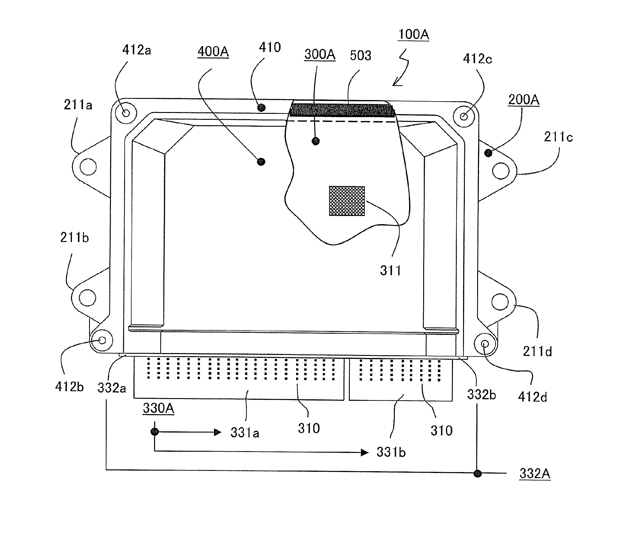
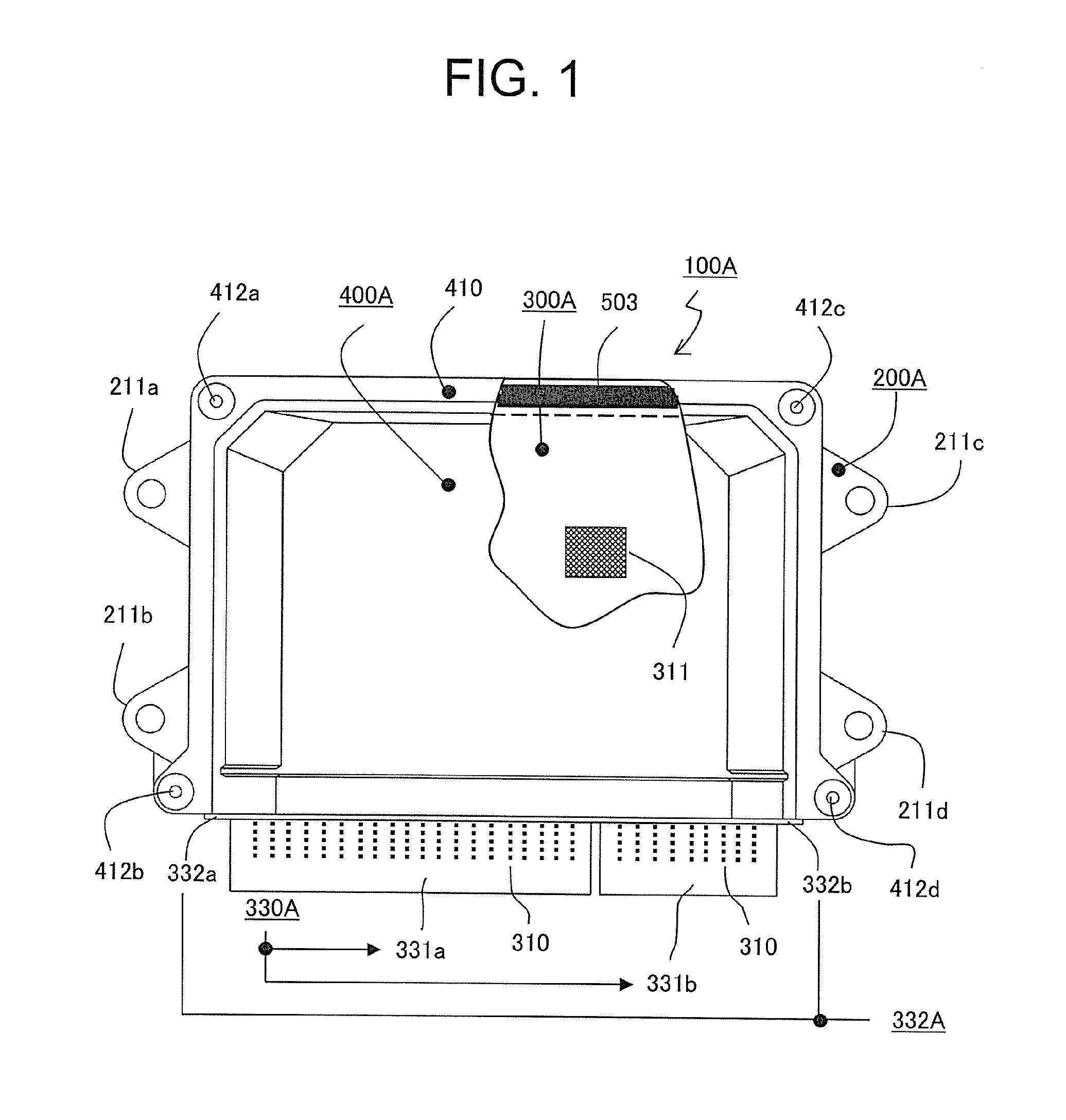
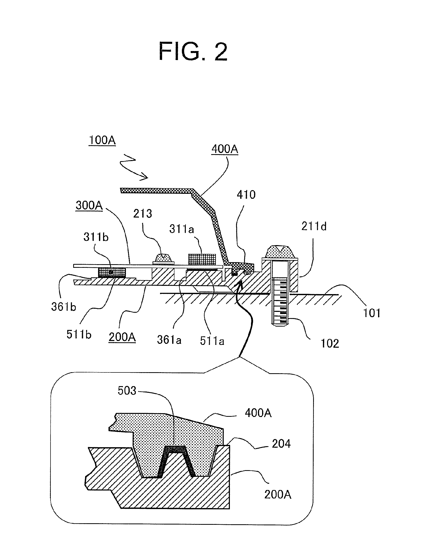
[0070]Now, descriptions are sequentially made of FIG. 1, which is a plan view illustrating a waterproof control unit according to a first embodiment of the present invention, FIG. 2, which is a view illustrating a mounting structure of the waterproof control unit of FIG. 1, FIG. 3, which is a detailed sectional view illustrating a connector housing of the waterproof control unit of FIG. 1, and FIG. 4, which is a plan view illustrating a cover side of the waterproof control unit of FIG. 1.

[0071]In FIG. 1, a waterproof control unit 100A includes a base 200A, a circuit board 300A, and a cover 400A. The base 200A includes four mounting legs 211a to 211d, and is formed by aluminum die casting. A plurality of circuit components 311 and heat generating components 311a and 311b (see FIG. 2) described later are mounted on the circuit board 300A. The cover 400A includes a flange 410 on three outer peripheral wall portions, and is made of resin. The remaining one outer peripheral wall portion ...

second embodiment

[0123]Now, referring to FIG. 8, which is a plan view illustrating a waterproof control unit according to a second embodiment of the present invention, FIG. 9, which is a partially detailed sectional view illustrating mounting of a circuit board of the waterproof control unit of FIG. 8, and FIG. 10, which is a detailed sectional view illustrating a connector housing of the waterproof control unit of FIG. 8, detailed descriptions are mainly made of differences from the waterproof control unit illustrated in FIGS. 1 to 5B. Note that, in the drawings, the same or corresponding parts are represented by the same reference symbols.

[0124]In FIG. 8, a waterproof control unit 100B includes abase 200B, a circuit board 300B, and a cover 400B. The base 200B includes right and left mounting legs 211B, and is formed by sheet metal working. The circuit components 311 and the heat generating components 311a and 311b described later are mounted on the circuit board 300B. The cover 400B includes a fla...


PUM

PropertyMeasurementUnit
widthaaaaaaaaaa
widthaaaaaaaaaa
dimensionaaaaaaaaaa

Abstract

In a waterproof control unit (100A) in which a part of a connector housing (330A) mounted on a circuit board (300A) is exposed and the circuit board (300A) is hermetically housed in a casing including a base (200A) and a cover (400A), in a gap between the cover and the connector housing, a waterproof sealing material (501) is applied to a first sealing gap defined by outer-step flat portions (401a,301a), slope portions (401b,301b), and inner-step flat portions (401c,301c), and in a gap between the base (200A) and the connector housing (330A) or between the base (200A) and the cover (400A), a waterproof sealing material (502,503) is applied to a second or third sealing gap defined by convexoconcave sealing surfaces having a convex thread loosely fitted into a concave thread.

Description

BACKGROUND OF THE INVENTION[0001]1. Field of the Invention[0002]The present invention relates to an improvement of a waterproof control unit, which is an on-vehicle electronic control device to be mounted in, for example, an engine compartment, and also relates to an improvement of a method of assembling the waterproof control unit.[0003]2. Description of the Related Art[0004]There have been widely used waterproof control units including a casing including a base and a cover and a circuit board hermetically housed in the casing, onto which a circuit component and a plurality of external connection contact terminals are mounted, and a connector housing made of a resin forming material is positioned and fixed, in which, in order to expose, from the casing, an end surface of the connector housing having the plurality of contact terminals passing therethrough, waterproof sealing materials filled into a first sealing gap defined between abutment surfaces of the connector housing and the ...

Claims


Application Information

Patent Timeline
Patent Type & Authority Applications(United States)
IPC IPC(8): H05K7/14B32B37/12B32B37/00B32B37/18
CPCH05K7/1427B32B37/18B32B37/1292B32B2605/08B32B2307/7265B32B2457/00B32B37/0076H05K5/0052H05K5/062
Inventor NURIYA, NOBUAKINISHIDA, MITSUNORINISHIZAWA, OSAMU
Owner MITSUBISHI ELECTRIC CORP
Why Eureka
Try Eureka