Removal of contaminants from bunker oil fuel

Active Publication Date: 2015-08-06
TRITON EMISSION SOLUTIONS
View PDF8 Cites 23 Cited by
  • Summary
  • Abstract
  • Description
  • Claims
  • Application Information

AI Technical Summary

Benefits of technology

[0013]After the emulsion exits from the second mixer stage, it passes through a microcavitation chamber in which the emulsion is subjected to high intensity acoustic waves that create cavitation bubbles in the emulsion, further increasing the separation of sulfur from the bunker oil. The emulsion then exits the microcavitation and enters a reactor chamber in which an electric current is passed through the emulsion. The electric current passing through the emulsion adds additional energy to further separate individual components of the emulsion. In particular, the electric current which passes through the emulsion will provide sufficient energy to strip some of the remaining sulfur atoms from the bunker oil. In addition, the electric current will provide sufficient energy to split some of the water molecules into the gaseous components of hydrogen and oxygen, creating bubbles of H2 and O2. The gas bubbles of hydrogen will have a great affinity for the sulfur and will create gas molecules of hydrogen sulfide, H2S, which can then be safely vented from the reactor chamber. In addition, some of the hydrogen sulfide may dissolve into the water and create a highly diluted hydrosulfuric acid. The electrolysis of the emulsion also creates oxygen gas from the splitting of the H2O molecule and the individual oxygen atoms quickly combine either with another oxygen atom to crea

Problems solved by technology

As a result, very low quality, dirty fuel has often been used in such vessels, sometimes called bunker oil or bunker fuel.
Traditional bunker oil is extremely crude and highly polluting.
Very little, if any, effort is made by the refining company to remove this sulfur from the bunker oil since this would take more time and money and raise the cost of the fuel oil significantly, with few regulations for burning high sulfur oil in a large cargo ship in the middle of the ocean, the oil is sold for this purpose.
Unfortunately, bunker oil is the commodity product which is widely produced in many locations in the world, and it is difficult and sometimes impossible to obtain bunker oil that does not have high contents of such pollutants, a particular problem being sulfur.
Since bunker oil having such a low sulfur content is not available on the market, many

Method used


Image

  • Removal of contaminants from bunker oil fuel
  • Removal of contaminants from bunker oil fuel
  • Removal of contaminants from bunker oil fuel

Examples


Embodiment Construction

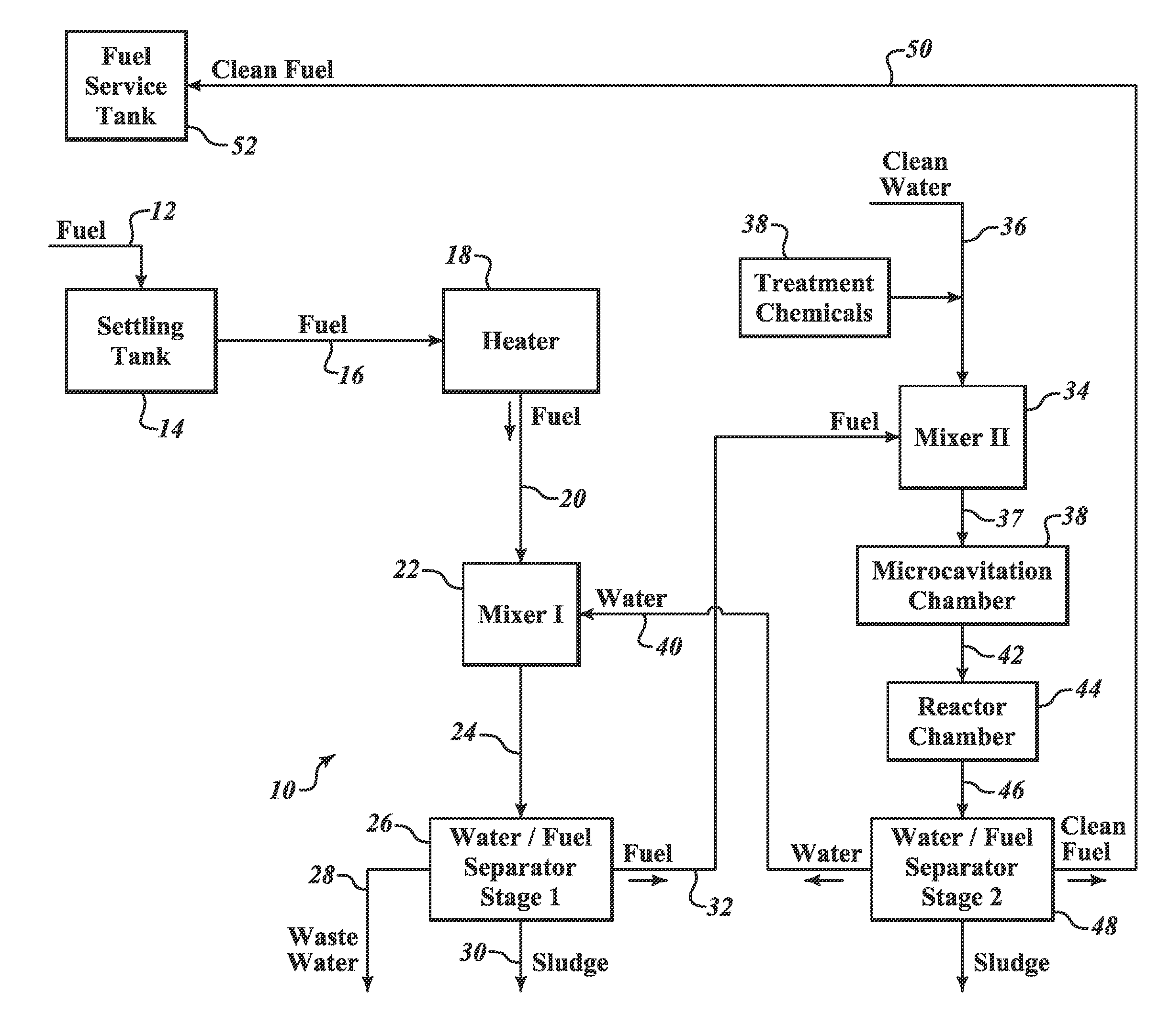
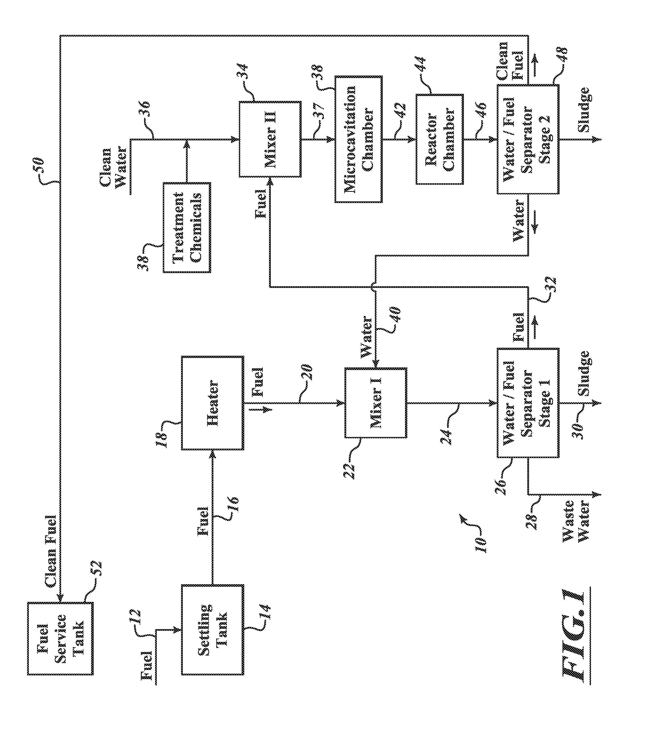
[0023]FIG. 1 is a block diagram of an apparatus 10 that is a system for cleaning bunker fuel to drive diesel engines of large cargo ships according to one embodiment.

[0024]The apparatus 10 has a fuel intake location 12 in which uncleaned bunker oil is input to a settling tank 14. The use of settling tanks at the beginning of cleaning systems for bunker fuels are well known in the art and therefore not described in greater detail. The present embodiment is an improvement upon a system that is the subject of a patent application previous filed bearing application Ser. No. 12 / 779,385 by the same inventor, Rasmus Norling. It was filed on May 13, 2010, as a continuation of an application filed on Nov. 16, 2008. The Norling application has been published as U.S. Patent Publication No. 2010 / 0276340, published on Nov. 4, 2010 (the '340 Publication”). The '340 Publication is a system for removing salt from fuel oil. The system as described therein is useful for removing such salt, however, i...


PUM


Abstract

A system and method for cleaning sulfur and other pollutants from bunker oil to be used for fuel in large cargo ships is described. Preferably, the system includes two or more stages having a mixer to create an emulsion of oil and water. One or more treatment chemicals are added to the water before it is mixed with the oil in order to assist in separating the sulfur from the oil and freeing it up so that it can combine with various other molecules present in the water or be dissolved in the water. The emulsion may pass through a microcavitation chamber as well as an electrolysis reactor chamber in order to further clean the fuel oil by removing additional sulfur content. The clean fuel is sent to a fuel service tank for use in a diesel engine combustion cycle.

Description

BACKGROUND[0001]1. Technical Field[0002]This invention is in the field of removing contaminants from diesel fuel and, in particular, the removal of particularly difficult and high pollution contaminants, such as sulfur.[0003]2. Description of the Related Art[0004]In the past, there have been few, if any, environmental regulations regarding the burning of diesel fuel by ocean-going vessels, such as large cargo ships, container ships, tankers, and luxury cruise liners. As a result, very low quality, dirty fuel has often been used in such vessels, sometimes called bunker oil or bunker fuel. Traditional bunker oil is extremely crude and highly polluting. During the refining of gasoline, higher quality fuel materials such as propane gas, gasoline for cars, and jet fuel are removed from the crude oil and the heavier petroleum products like diesel oil and lubricating oil are then removed leaving bunker oil as the last residue. The bunker oil may therefore contain a high amount of sulfur, o...

Claims


Application Information

Patent Timeline
IPC IPC(8): B01J19/08B01J19/00
CPCB01J19/008B01J19/088C10G31/06C10G31/08C10G2300/202C10G53/04C10G53/12C10G19/02C10G21/06C10G33/02
Inventor NORLING, RASMUS
Owner TRITON EMISSION SOLUTIONS
Why Eureka
Try Eureka