Image processing system, and image processing method

a technology of image processing and image processing, applied in the field of image processing system and image processing method, can solve the problems of low resolution for reconstruction, decoding errors tend to occur, and 3d scanners that measure static scenes cannot perform shape measurement as accurately and densely as existing scanners

Active Publication Date: 2015-08-06
HIROSHIMA CITY UNIVERSITY +2
View PDF3 Cites 23 Cited by
  • Summary
  • Abstract
  • Description
  • Claims
  • Application Information

AI Technical Summary

Benefits of technology

[0036]As described above, according to the present invention, since shape reconstruction is performed for a grid pattern formed of wave lines based on

Problems solved by technology

As for currently employed moving object scanners, 3D scanners that measure static scenes cannot perform shape measurement as accurately and densely as existing scanners.
An appropriately large area is required for this process, and therefore, the resolution for reconstruction tends to be low.
Furthermore, decoding errors tend to occur due to, for example, distortion of a pattern caused by the change of the surface shape.
Further, for projectors available on the market, spectral distributions of the individual color components are overlapped each other, and therefore, an error tends to occur in determination of colors for individual pixels.
However, the problems on ambiguities of correspondences and sparse reconstruction have not yet been resolved.
Since measurement is performed for one point at a time, it is unsuitable for measurement of a large region in a short period of time.
However, the present systems are easily affected by the interference of other light

Method used


Image

  • Image processing system, and image processing method
  • Image processing system, and image processing method
  • Image processing system, and image processing method

Examples


first embodiment

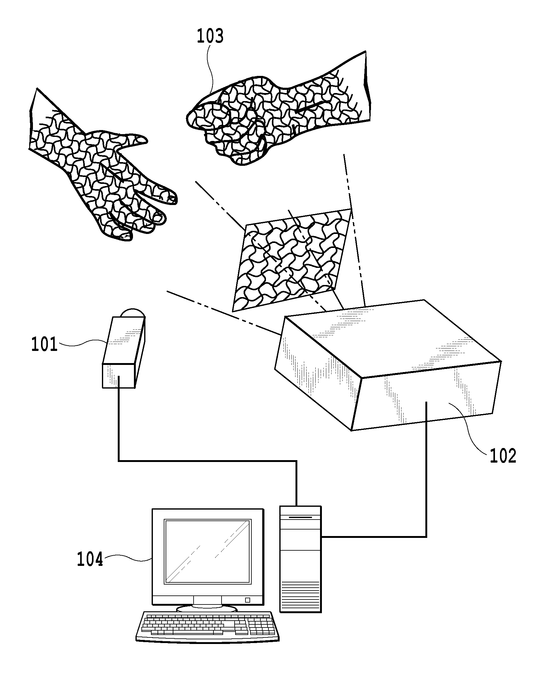
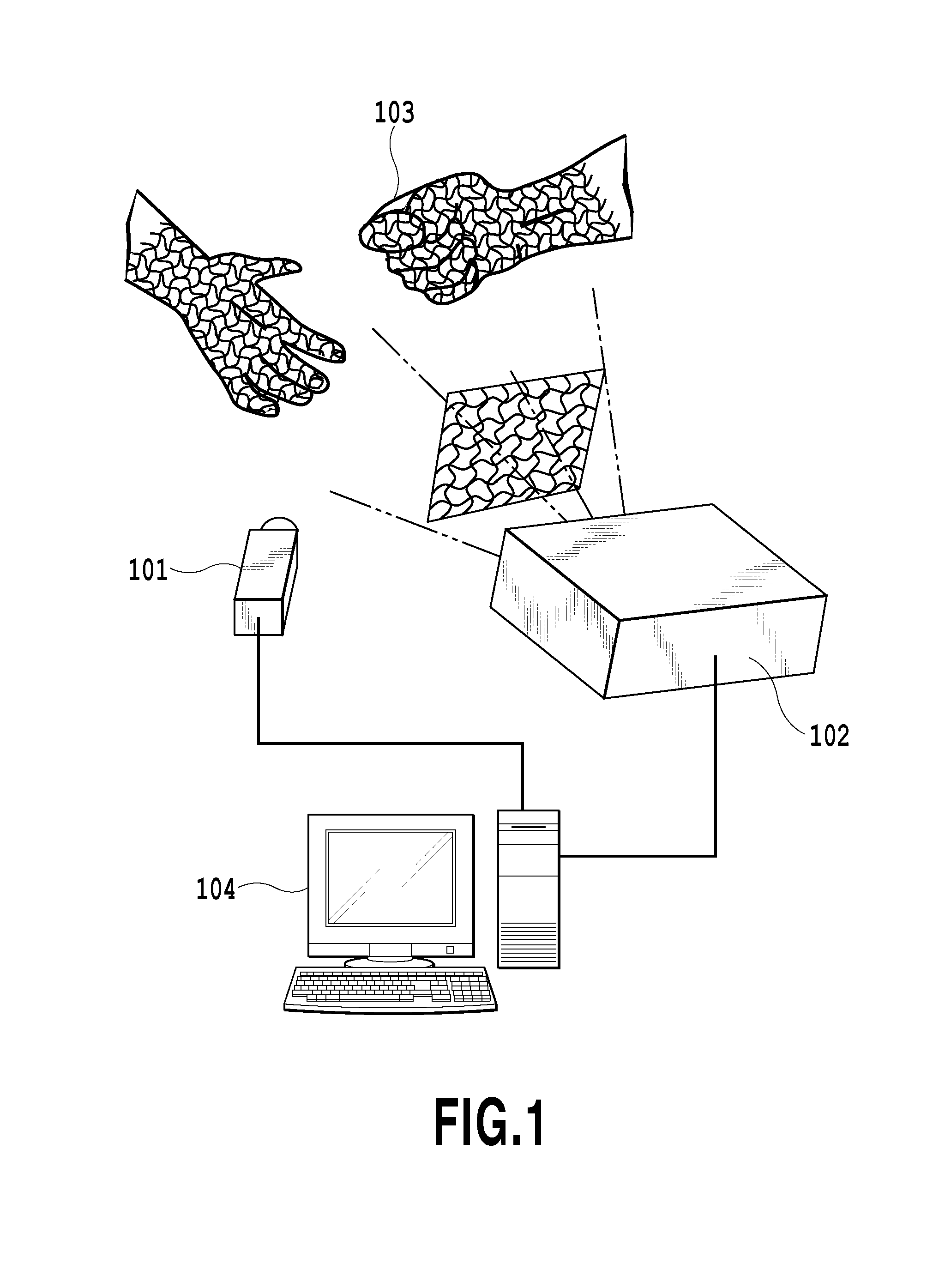
[0089]An image processing system according to a first embodiment of the present invention is illustrated in FIG. 1. One camera 101 (imaging device) and one projector 102 (projection device) are employed. The projector 102 projects, to an observation target 103, a grid pattern formed of wave lines. Since a projected pattern is a static pattern, synchronization with projection is not required. Therefore, measurement with a very high FPS (Frames Per Second) is enabled. The camera 101 and the projector 102 are connected to an image processing apparatus 104 that includes a personal computer.

[0090]The image processing apparatus 104 stores projected patterns, such as grid patterns formed of wave lines, in a storage medium in advance, and can transmit projected pattern data to the projector 102 to project the pattern to the observation target 103. Further, the image processing apparatus 104 fetches an input image captured by the camera 101, stores the input image in the storage medium, and ...

second embodiment

[0114]An image processing system according to a second embodiment of the present invention is illustrated in FIG. 7. Two cameras 1101 and 1102 (imaging devices) and one projector 1103 (projection device) are employed. The projector 1103 projects, to an observation target 1104, a grid pattern formed of wave lines. Since a projected pattern is a static pattern, synchronization with projection is not required. Therefore, measurement with a very high FPS (Frames Per Second) is enabled. The cameras 1101 and 1102 and the projector 1103 are connected to an image processing apparatus 1105 that includes a personal computer.

[0115]The image processing apparatus 1105 stores projected patterns, such as grid patterns formed of wave lines, in a storage medium in advance, and can transmit projected pattern data to the projector 1103 to project the pattern to the observation target 1104. Further, the image processing apparatus 1105 fetches input images captured by the cameras 1101 and 1102, stores t...

third embodiment

[0125]An image processing system according to a third embodiment of the present invention is illustrated in FIG. 10. Six cameras 2101 to 2106 (imaging devices) and six projectors 2201 to 2206 (projection devices) are employed. The projectors 2201 to 2206 project, to an observation target 2301, grid patterns formed of wave lines. Since projected patterns are static patterns, synchronization with projection is not required. Therefore, measurement with a very high FPS (Frames Per Second) is enabled. The cameras 2101 to 2106 and the projectors 2201 to 2206 are connected to an image processing apparatus 2401 that includes a personal computer.

[0126]The image processing apparatus 2401 stores projected patterns, such as grid patterns formed of wave lines, in a storage medium in advance, and can transmit projected pattern data to the projectors 2201 to 2206 to project the patterns to the observation target 2301. Further, the image processing apparatus 2401 fetches input images captured by th...


PUM


Abstract

A high-density shape reconstruction is conducted in measuring animal bodies as well. An image processing system has a projection device, an imaging device, and an image processing apparatus connected to the projection device and the imaging device, wherein the projection device projects a projected pattern to an observation target, the imaging device captures the projected pattern, and the image processing apparatus performs shape reconstruction based on an input image including the projected pattern. The image processing apparatus includes a unit for fetching the input image captured by the imaging device and performing line detection for the projected pattern projected by the projection device, wherein the projected pattern is a grid pattern formed of wave lines; and a unit for performing shape reconstruction by associating intersection points of vertical and horizontal lines extracted by the line detection with the projected pattern.

Description

TECHNICAL FIELD[0001]The present invention relates to an image processing system and an image processing method, and more particularly to an image processing system and an image processing method for performing dense shape reconstruction based on one-shot 3D measurement using a single-colored pattern.BACKGROUND ART[0002]In recent years, an attention has been drawn on reconstruction of a 3D moving scene. A great success has been achieved on, for example, a gaming product that serves as a device-free interface by measuring a human body in real time, and analyzing the motion of the human body (see, for example, NPL 1). Further, a research for employing such a product as the eyes of an autonomous mobile robot has been continued, and the importance of measurement of a moving object has been strongly noticed. As for currently employed moving object scanners, 3D scanners that measure static scenes cannot perform shape measurement as accurately and densely as existing scanners. However, if ...

Claims


Application Information

Patent Timeline
IPC IPC(8): G06T7/00G01B11/25
CPCG06T7/0057G06T2207/10012G06T1/00G01B11/2545G01B11/2513G06T1/0007G06T7/521G06T7/73
Inventor SAGAWA, RYUSUKEKAWASAKI, HIROSHIFURUKAWA, RYO
Owner HIROSHIMA CITY UNIVERSITY
Why Eureka
Try Eureka