Hidden window antenna

Active Publication Date: 2015-08-06
PITTSBURGH GLASS WORKS
View PDF7 Cites 23 Cited by
  • Summary
  • Abstract
  • Description
  • Claims
  • Application Information

AI Technical Summary

Benefits of technology

[0006]The presently disclosed invention concerns a slot antenna that is suitable for use in vehicle applications. The disclosed antenna has improved impedance matching and frequency tu

Problems solved by technology

Electrical currents that flow on the coating surface result in resistance losses that impair antenna performance.
Most of

Method used


Image

  • Hidden window antenna
  • Hidden window antenna
  • Hidden window antenna

Examples


Example

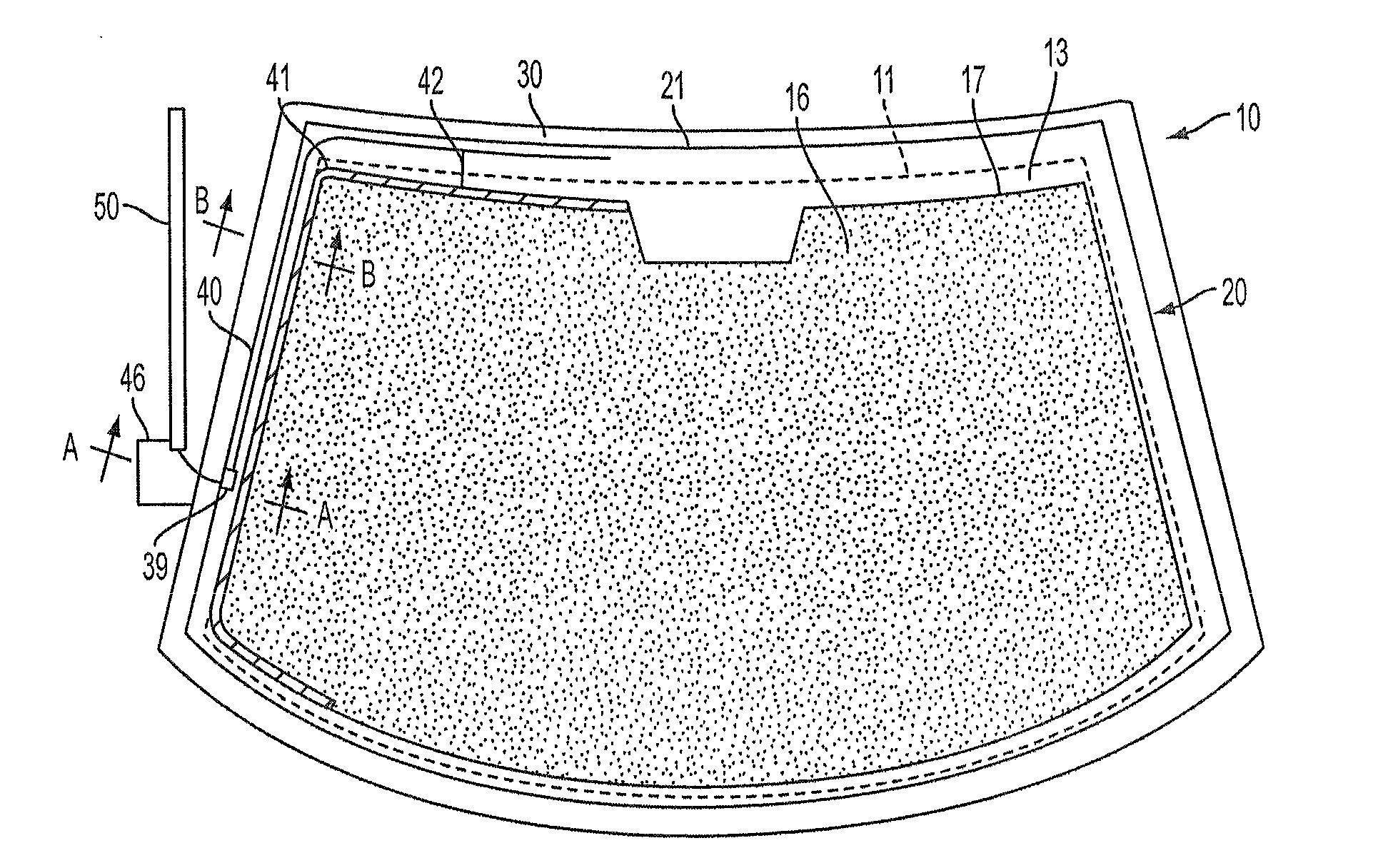
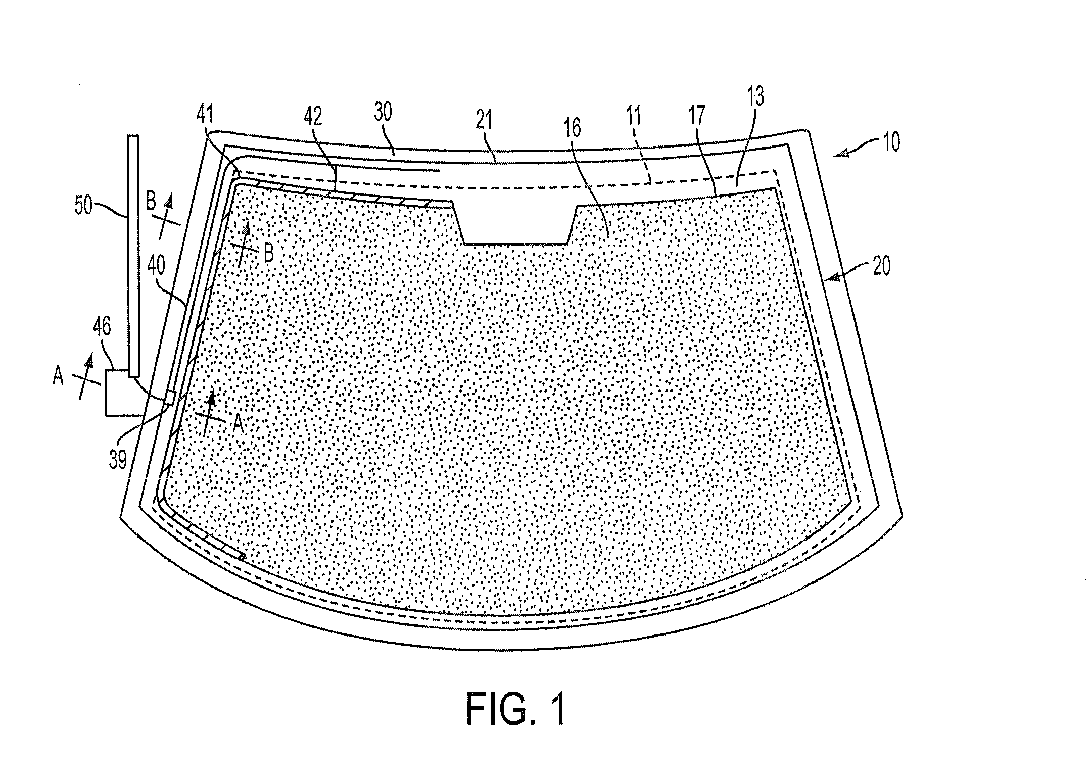
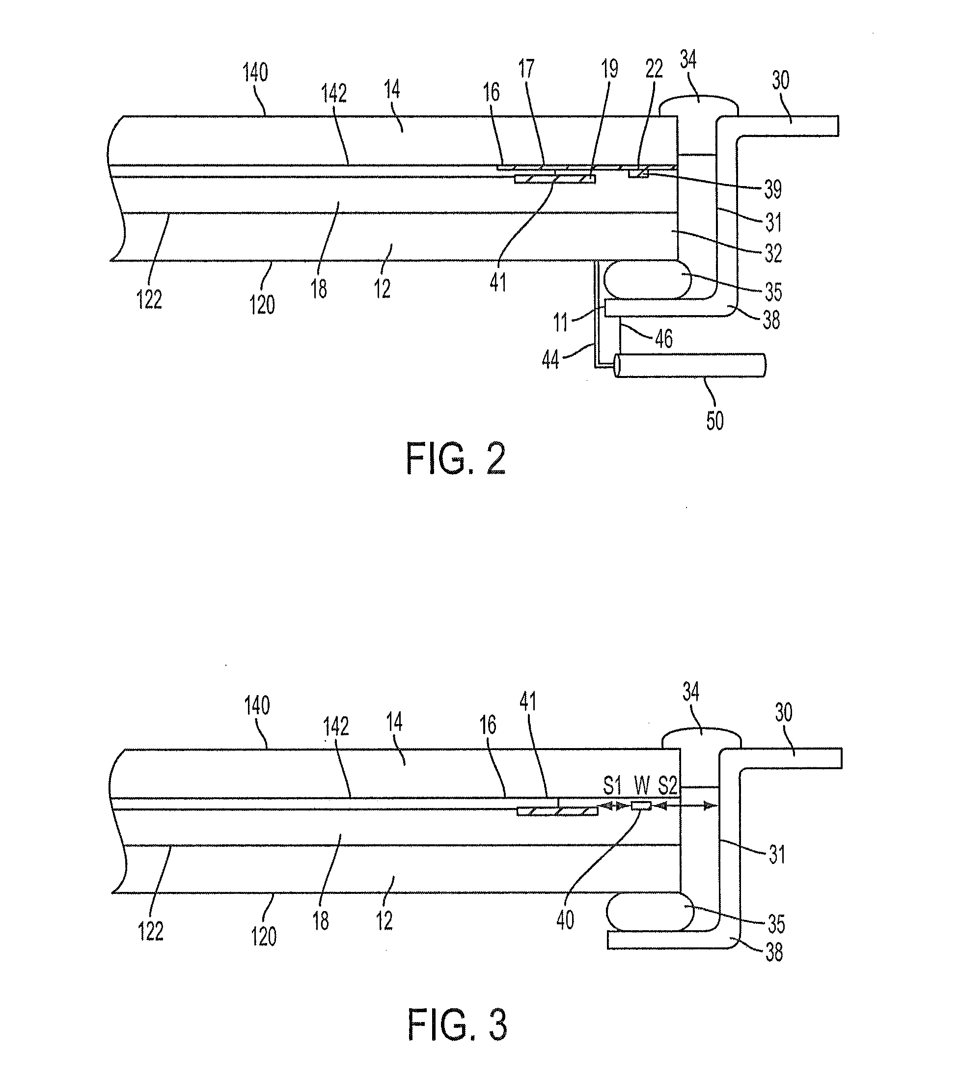
[0018]FIG. 1 is a plan view of transparent antenna windshield 10 and associated structure incorporating features of the presently disclosed invention. The windshield 20 is surrounded by a metal frame, which has a window aperture that is defined by window edge 11 of body 30. The outer edge 21 of windshield 20 overlaps the annular flange 38 of body 30 to provide, in this embodiment, a windshield for vehicle body 30. As shown in FIG. 2, an annular sealing member 35 is located between window glass 20 and flange 38; and a molding 34 bridges the outer gap between the body 30 and windshield 20. The window opening is defined by the edge 11 and surface 31 of vehicle body 30.

[0019]Windshield 20 is a laminated vehicle windshield formed of outer and inner glass plies 14 and 12 bonded together by an interposed layer 18, preferably of a standard polyvinylbutyral or similar plastic material. Outer glass ply 14 has an outer surface 140 (conventionally referred to as the number 1 surface) on the out...


PUM


Abstract

A vehicle slot antenna wherein an electro-conductive coating is applied to the surface of a glass ply. The peripheral edge of the conductive coating is spaced from the vehicle window edge and connected to a high conductive bus bar to define an annular slot antenna with low resistance loss and improved antenna efficiency. The slot antenna is fed by a thin conductive line located in the middle of the slot and parallel to the bus bar. The thin line along with the conductive coating and window frame form a coplanar waveguide (CPW). The CPW feed provides a convenient feed for the antenna at any point around the perimeter of the window slot and affords antenna tuning and impedance matching. The antenna design can use the characteristic impedance of the CPW line to match the impedance of the slot antenna to the impedance of a coaxial cable or other input impedance.

Description

TECHNICAL FIELD[0001]The present invention relates generally to vehicle antennas and, more particularly, to an antenna formed in association with a transparent ply having an electrically conductive coating.BACKGROUND OF THE INVENTION[0002]Antennas have been proposed which use the theory of operation of quarter or half wavelength antenna in combination with a vehicle window having a thin IR reflective film or conductive coating on or between the layers of the glass window. For example, U.S. Pat. Nos. 4,849,766, 4,768,037, and 4,864,316 illustrate a variety of antenna shapes that are formed by a thin film on a vehicle window. U.S. Pat. No. 5,670,966 discloses an automotive antenna having several electrically interconnected coating regions. U.S. Pat. Nos. 5,083,135 and 5,528,314 illustrate a vehicle antenna having a transparent coating in the shape of a “T”. U.S. Pat. No. 6,448,935 discloses an antenna having a two-piece conductive coating that is used as AM and FM antenna that are sep...

Claims


Application Information

Patent Timeline
IPC IPC(8): H01Q1/12H01Q13/10H01Q1/27
CPCH01Q1/1271H01Q13/10H01Q1/27
Inventor DAI, DAVID
Owner PITTSBURGH GLASS WORKS
Why Eureka
Try Eureka