Method of and Receiver for Communication During Wireless Power Transmission

a wireless power transmission and receiver technology, applied in transmission, transformers, inductances, etc., can solve the problems of reducing affecting the efficiency of transmission, so as to reduce the size of the filtering capacitor 10 and reduce the degradation of communication signals. , the effect of efficient power reception

Inactive Publication Date: 2015-08-06
OPTIS CIRCUIT TECH LLC
View PDF6 Cites 10 Cited by
  • Summary
  • Abstract
  • Description
  • Claims
  • Application Information

AI Technical Summary

Benefits of technology

[0019]The fourth aspect of the invention aims to reduce efficiency losses in the power transmission which may be caused by the communication process.

Problems solved by technology

The rectification of the power carrying wave induces significant noise harmonics on the operation frequency, especially the second harmonic.
Eventually, as the capacitor size increases this will cause bit read errors resulting in the deterioration of the Bit Error Rate (BER) of the communication channel below an acceptable level.
As information is tied to pulse duration, the malformation of the shape of the current pulse will lead to demodulation errors if deviation is allowed to grow large enough.
Consequently the size of the filtering capacitor is limited by the tolerable distortion of the generated current pulse.
This, in turn, makes it more difficult to perform the current measurement with desired accuracy as the analogue circuitry must now tolerate higher noise level.

Method used


Image

  • Method of and Receiver for Communication During Wireless Power Transmission
  • Method of and Receiver for Communication During Wireless Power Transmission
  • Method of and Receiver for Communication During Wireless Power Transmission

Examples


Embodiment Construction

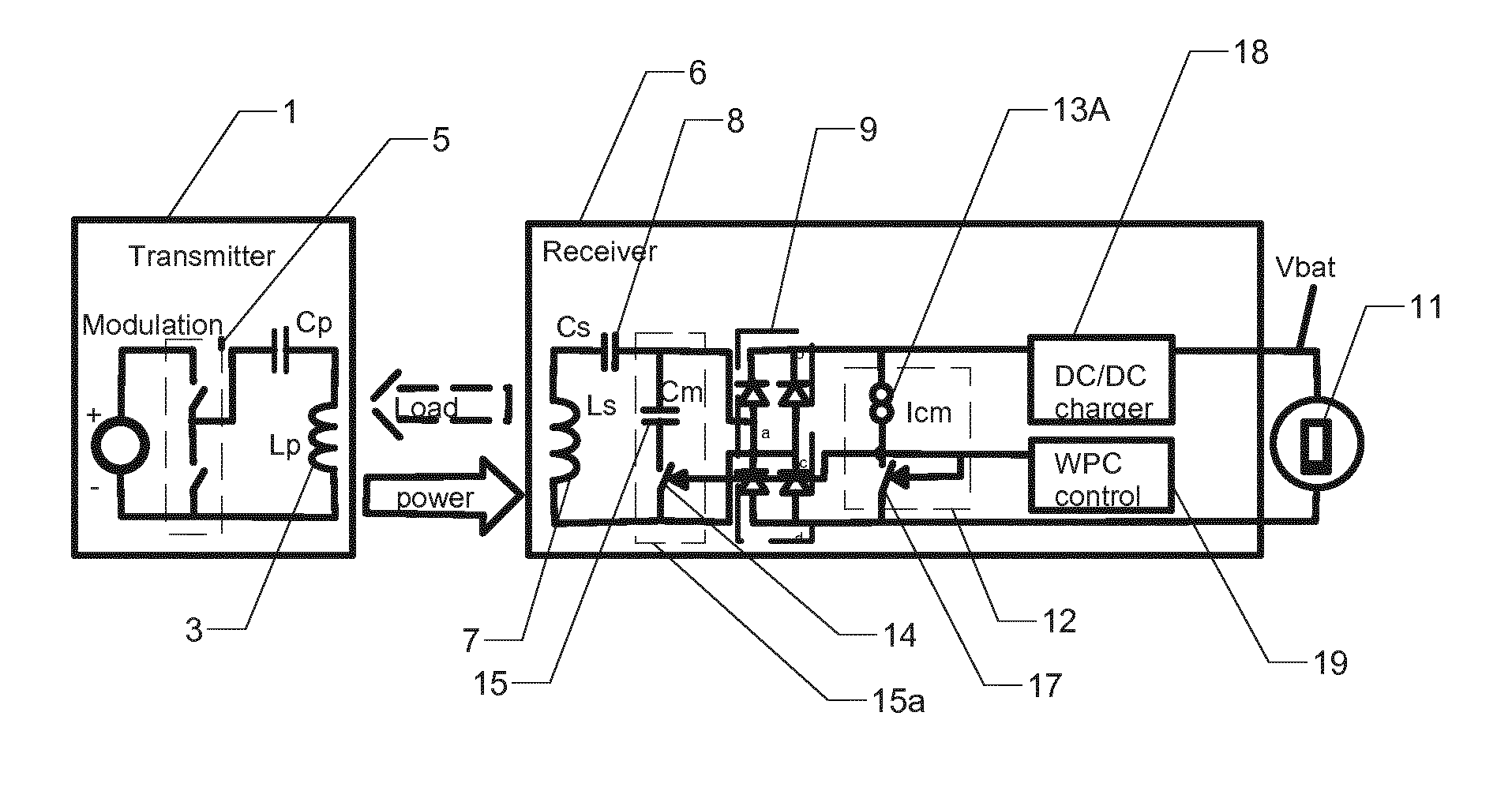
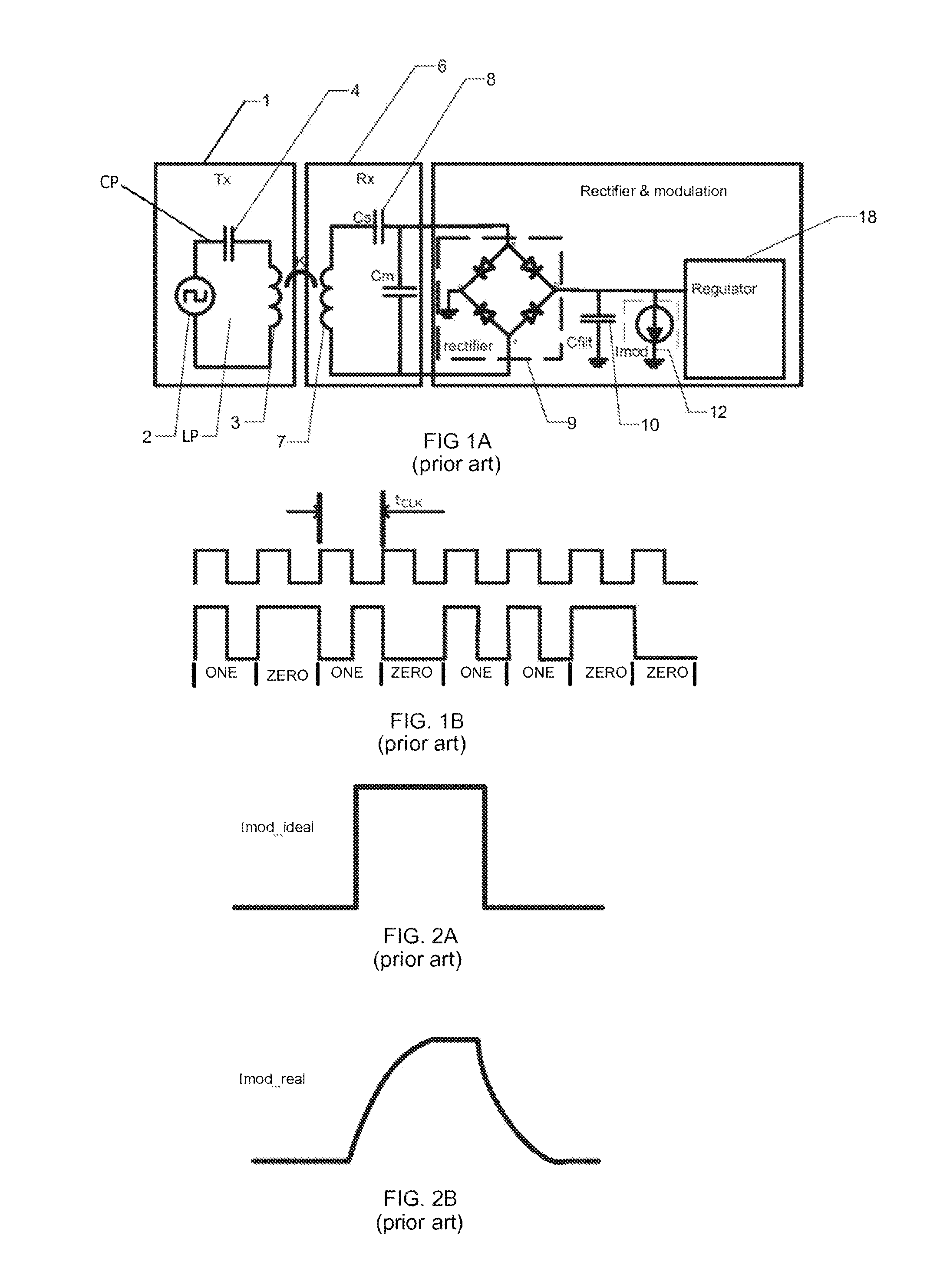
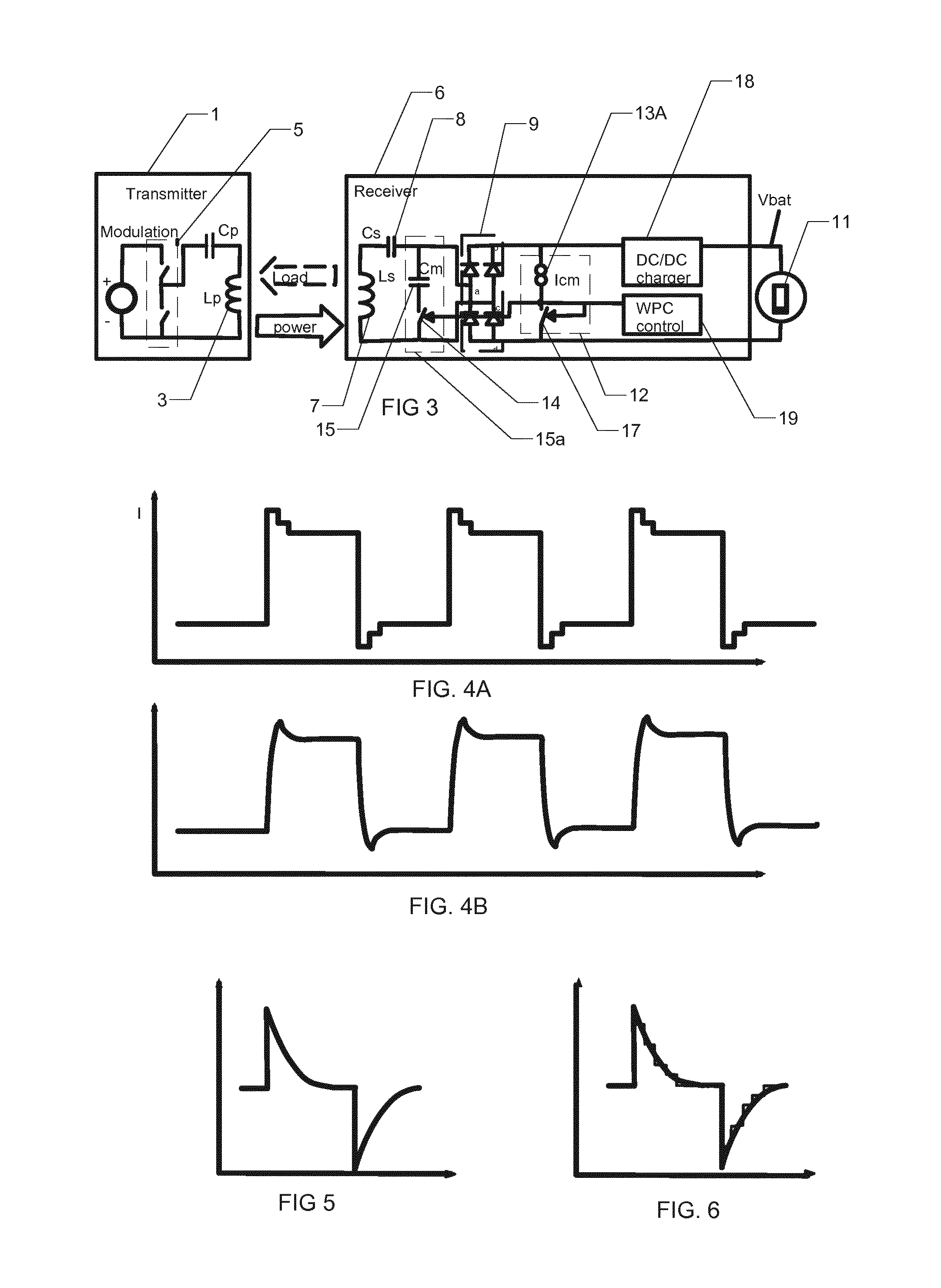
[0030]FIG. 4A schematically illustrates an idealised pre-distorted current pulse and the resulting current pulse that flow towards the transmitter 1 (TX). FIG. 4B shows a practical form of the signal pulse seen at the secondary inductor 7. As a result it is possible to use larger filtering capacitors than the prior art arrangement, resulting in better accuracy of measurements. Moreover, should there be other sources of error within the system, such as transients in load current, the ability to produce better shaped pulses makes the system more insensitive to other types of distortion or noise.

[0031]An example of a harmful transient current flowing through capacitor is illustrated in FIG. 5. In order to compensate its impact, a pulse generating current modulator 12 is controlled by a controller 19, so that it effectively adds (superposes) a discrete replica of the transient current on top of the ideal pulse rectangular step function pulse. An example for this is shown in FIG. 6. This...


PUM


Abstract

In a wireless power charger a receiver (6) is inductively coupled to a transmitter (1) to receive power for charging an accumulator in a device (11). The receiver (6) communicates charging data to the transmitter (1) by imposing current pulses across the direct current output terminals of a rectifier (9) in the receiver. To enhance the performance of the receiver without reducing the signal to noise ratio of the current pulse receiver to transmitter communication the shape of unwanted transient currents in a filter capacitor (10) are sensed and the transient current shape added to an ideal rectangular step function pulse shape to produce a communication pulse shape. As a result the communication pulse shape seen at a secondary inductor (7) of the receiver closely approximates the ideal rectangular step function shape desired whereby the signal to noise ratio is kept high. The receiver is particularly useful in mobile devices such as cell phones, tablet PC's and laptops.

Description

TECHNICAL FIELD[0001]The present invention concerns communication between a receiver and transmitter during inductive wireless transmission of electric charge from the transmitter to the receiver.BACKGROUND[0002]The Wireless Power Consortium (WPC) publishes the specification: “System Description Wireless Power Transfer Volume I: Low Power Part 1: Interface Definition” at (http: / / www.wirelesspowerconsortium.com). Chapter 6 “Communication Interface” is of particular relevance to this application and versions of this specification predating this application are incorporated herein, in their entirety, by reference. The following discussion of the prior art reiterates some of the most relevant parts of the specification.[0003]FIG. 1 A illustrates a prior art transmitter and receiver. A transmitter 1 (Tx) is provided with a power supply 2 which drives AC current through a circuit including a primary inductor 3 (Lp) and a capacitor 4 (Cp). The transmission circuit is modulated by a modulat...

Claims


Application Information

Patent Timeline
Patent Type & Authority Applications(United States)
IPC IPC(8): H04B5/00H02J5/00
CPCH04B5/0037H02J17/00H02J5/005H02J50/10H02J7/00714H02J50/80H02J50/12
Inventor RAPAKKO, HARRILINTONEN, MIKKOPESSA, MARKO
Owner OPTIS CIRCUIT TECH LLC
Why Eureka
Try Eureka