Shared aperture antenna array

a technology of aperture antenna array and aperture antenna, which is applied in the direction of polarised antenna unit combination, using reradiation, instruments, etc., can solve the problem that the physical size of the antenna cannot be greatly reduced to achieve any noticeable increase in sampling density, and achieve the effect of increasing sampling density

Active Publication Date: 2015-08-13
BATTELLE MEMORIAL INST
View PDF9 Cites 14 Cited by
  • Summary
  • Abstract
  • Description
  • Claims
  • Application Information

AI Technical Summary

Benefits of technology

[0017]In another embodiment of the present invention, a method of increasing sampling density using a shared aperture antenna array is disclosed. The method includes providing an array of antennas; and creating additional antennas by sharing elements of neighboring antennas within the array.

Problems solved by technology

The continuing challenge with the development of antenna arrays used in holographic imaging applications is to reduce the size and weight and achieve adequate physical sampling / pixel spacing in the array.
Since the physical size of the antenna is constrained by the bandwidth of operation, the physical size of the antennas cannot be greatly reduced to achieve any noticeable increase in sampling density.

Method used


Image

  • Shared aperture antenna array
  • Shared aperture antenna array
  • Shared aperture antenna array

Examples


Embodiment Construction

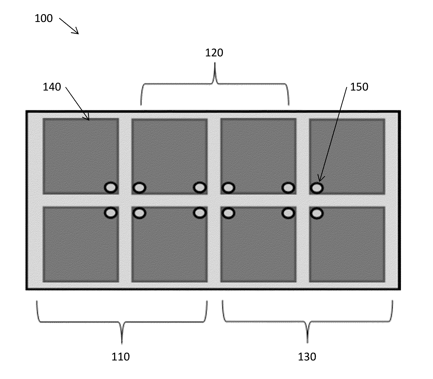
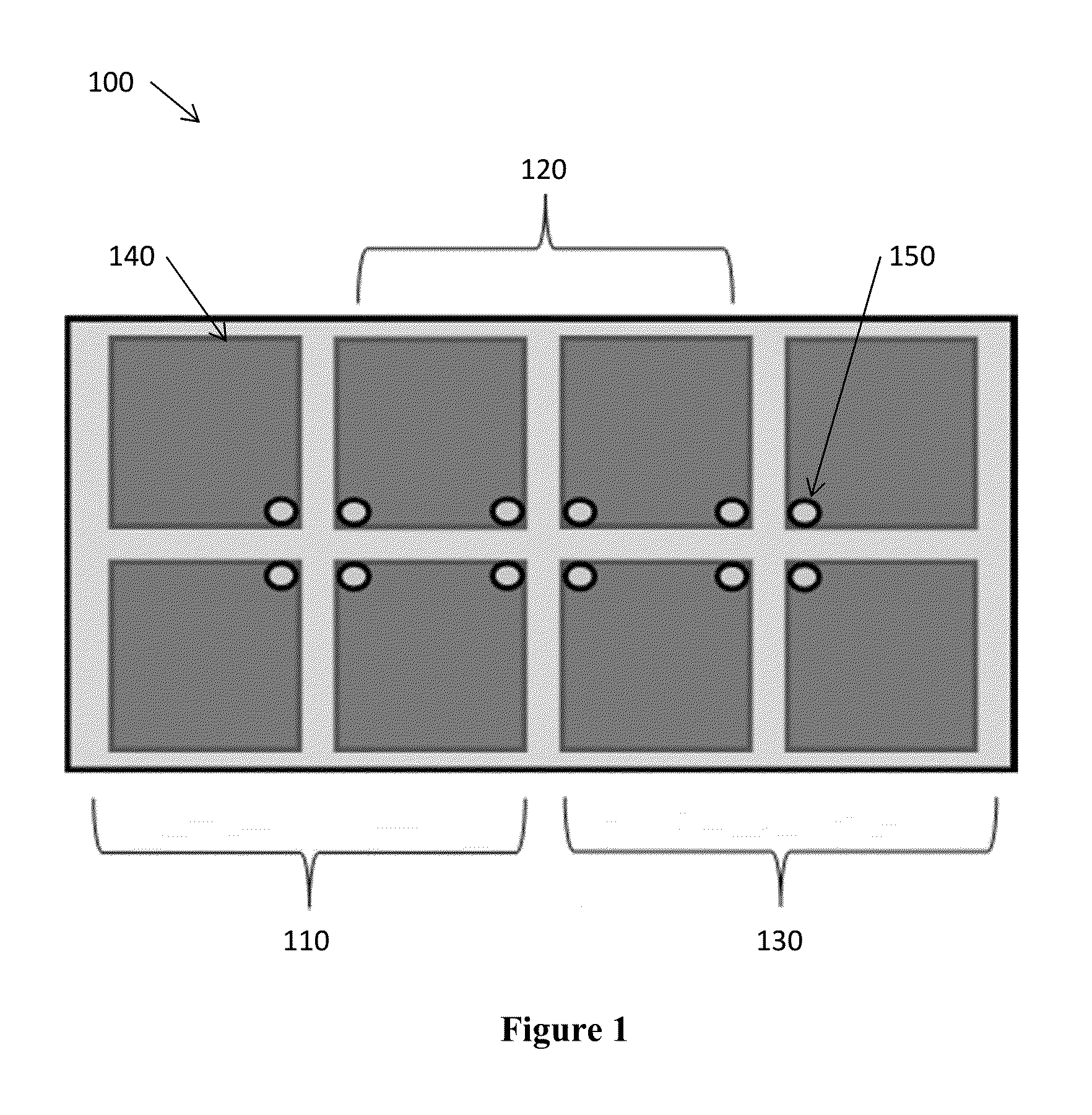
[0023]The present invention describes an array of antennas that shares components or elements of neighboring antennas to create additional antennas. The shared aperture array creates additional antenna elements within an array of broadband planar dipole antennas, allowing for increased array sampling and pixel density than current antenna array designs. The shared aperture array can achieve pixel sampling distances much smaller than one-half wavelength with a single array of antennas. The sharing of elements of neighboring antennas to create additional antennas reduces the physical size of the arrays by a factor of two, allows for fully polarimetric data sets with a single array, increases the physical sampling—reducing pixel sampling in the array—to one-twelfth of a wavelength, and enables imaging systems with reduced weight.

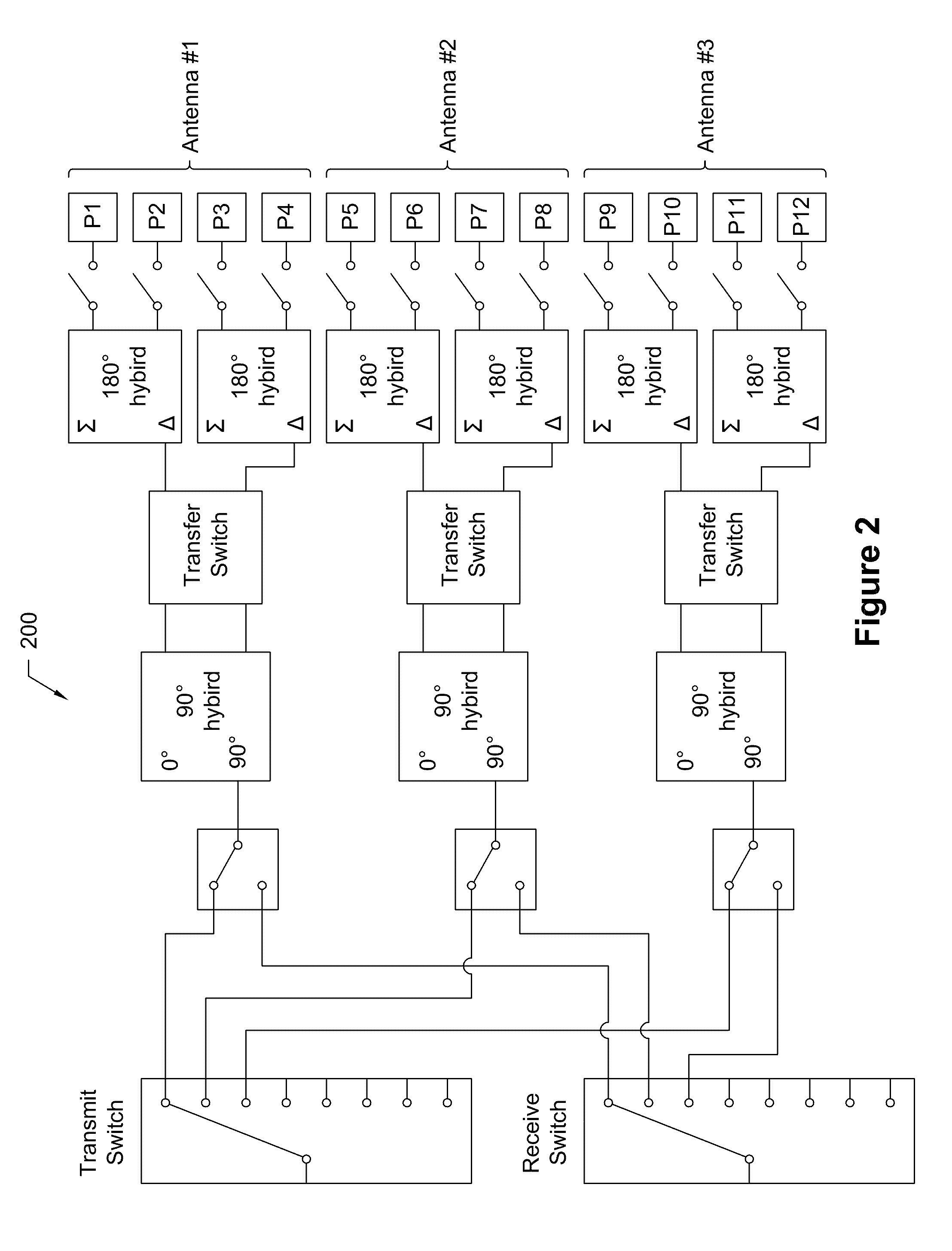
[0024]In one embodiment, the present invention discloses an array of broadband planar dipoles and maintains desirable circular polarization properties of trans...


PUM


Abstract

A shared aperture antenna array including an array of antennas is disclosed. Elements of neighboring antennas are shared to create additional antennas. The shared elements include radiating patches and apertures. Each antenna shares an aperture with neighboring antennas. The array of antennas may be linear or two-dimensional. A phase shifting network with single-pole-single-throw reflective switches may be coupled to the antennas.

Description

STATEMENT REGARDING FEDERALLY SPONSORED RESEARCH OR DEVELOPMENT[0001]This invention was made with Government support under Contract DE-AC05-76RLO1830 awarded by the U.S. Department of Energy. The Government has certain rights in the invention.TECHNICAL FIELD[0002]This invention relates to antenna arrays. More specifically, this invention relates to a shared aperture antenna array wherein elements or portions of neighboring antennas are shared to create additional antennas.BACKGROUND OF THE INVENTION[0003]Current technologies for linear and two-dimensional radar imaging antenna arrays use sequential sampling, synthetic apertures, and sparse array techniques to achieve sampling / pixel density. All of these techniques focus on switching networks to use antennas in the array as transmitters / receivers. For example, linear holographic radar imaging arrays typically use two separate linear arrays of cavity-backed spiral antennas to transmit and receive circularly polarized signals.[0004]Mic...

Claims


Application Information

Patent Timeline
Patent Type & Authority Applications(United States)
IPC IPC(8): G01S13/02H01Q21/00G01S7/03H01Q9/28
CPCG01S13/02H01Q9/285G01S2013/0254G01S7/03H01Q21/0006H01Q9/0435H01Q21/062H01Q21/24
Inventor TEDESCHI, JONATHAN R.JONES, A. MARK
Owner BATTELLE MEMORIAL INST
Why Eureka
Try Eureka