System and method for transmitting optical signal over multiple channels

Active Publication Date: 2015-08-13
NEC CORP
View PDF2 Cites 42 Cited by
  • Summary
  • Abstract
  • Description
  • Claims
  • Application Information

AI Technical Summary

Benefits of technology

[0026]An exemplary advantage according to the invention is to improve the system margin

Problems solved by technology

However, this increase in the transmission capacity of the system requires a high complexity in the transmitters and receivers.
In addition, the tr

Method used


Image

  • System and method for transmitting optical signal over multiple channels
  • System and method for transmitting optical signal over multiple channels
  • System and method for transmitting optical signal over multiple channels

Examples


first exemplary embodiment

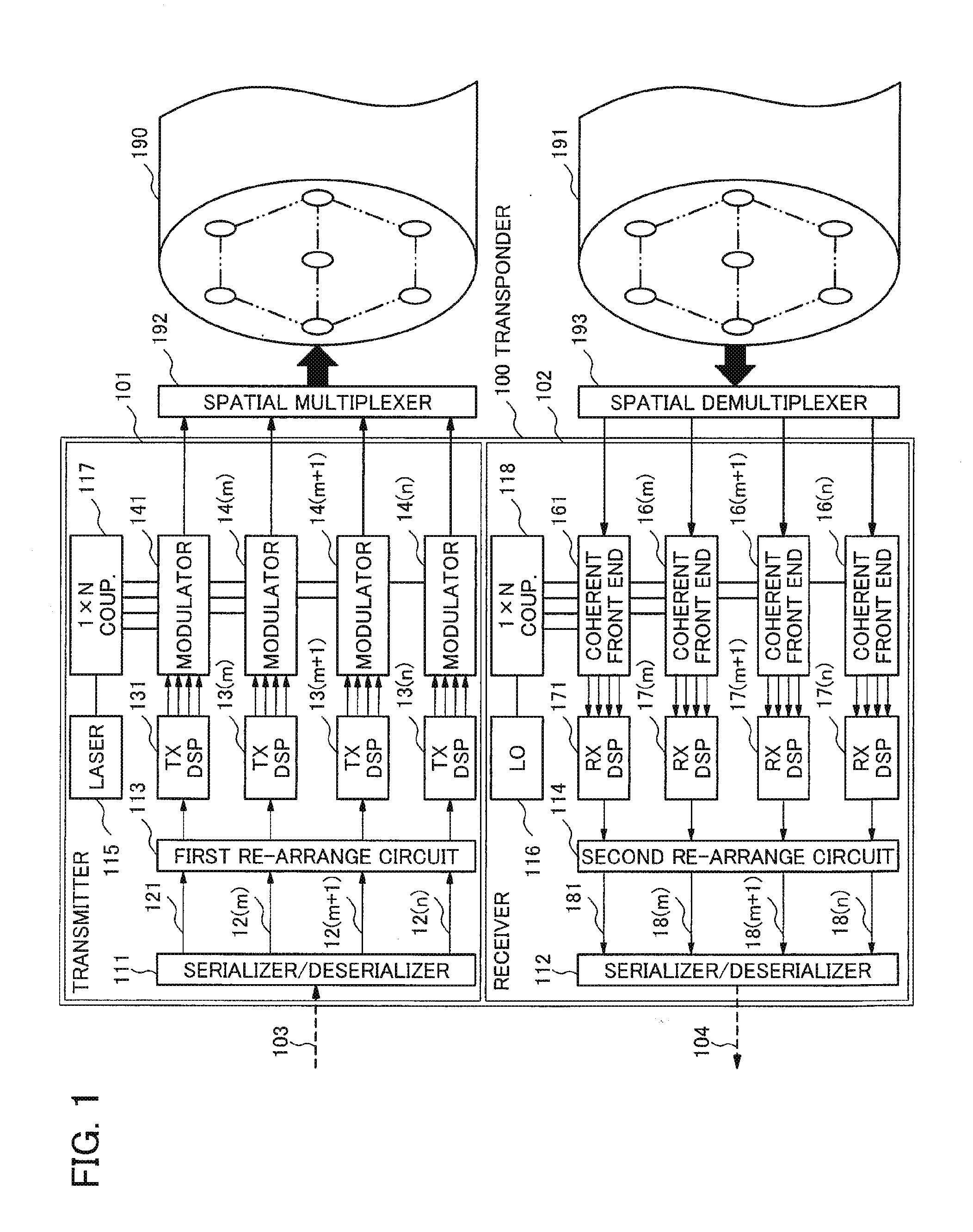
[0033]FIG. 1 is a schematic representation of an optical transponder 100, including an optical transmitter 101 and an optical receiver 102. The optical transmitter 101 emits n-tuple parallel optical signals according to a binary data stream 103. A spatial multiplexer 192 multiplexes the n-tuple optical signals emitted by the optical transmitter 101 into a multicore optical fiber 190 which has multiple channels, that is, n-tuple cores, where “n” is an integer and is equal to or more than 2 (n≧2). Alternatively, the spatial multiplexer 192 can be integrated into the optical transmitter 101 or in the transponder 100.

[0034]A serializer / deserializer 111 converts the binary data stream 103 into n-tuple parallel tributaries denoted by the numerals from 121 to 12(n) on FIG. 1. Considering the integer “m” which is equal to or more than 2 and is less than or equal to “n” (2≦m≦n), a first re-arrange circuit 113 rearranges the data contained in m-tuple tributaries denoted by the numerals from 1...

second exemplary embodiment

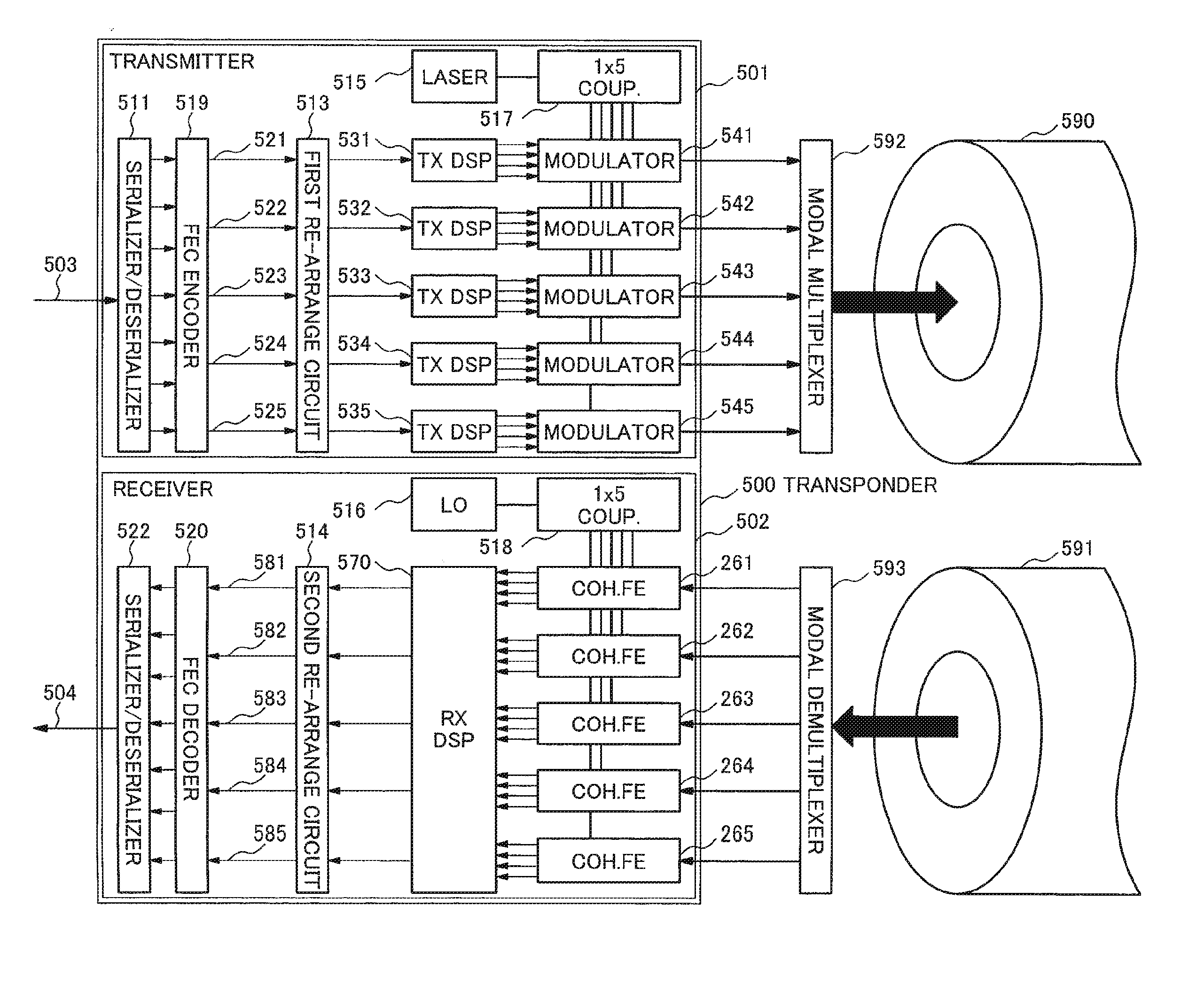
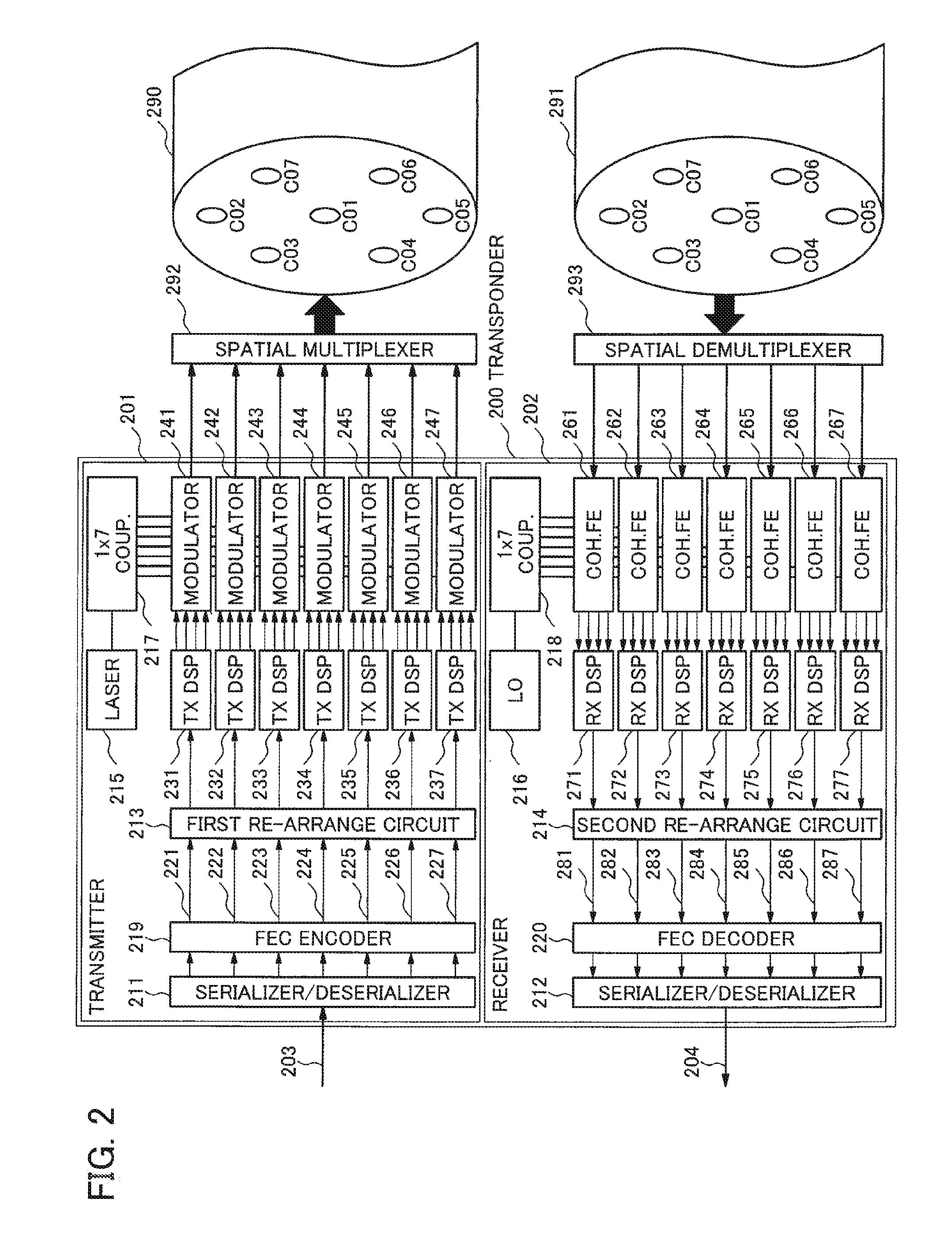
[0046]FIG. 2 is a schematic representation of an optical transponder 200. The optical transponder 200 includes an optical transmitter 201 and an optical receiver 202. The optical transmitter 201 emits 7 optical signals according to a binary data stream 203. For the case of n=7 and m=n=7, a spatial multiplexer 292 and a multicore optical fiber 290 are similar to the spatial multiplexer 192 and the multicore optical fiber 190 on FIG. 1, respectively.

[0047]A serializer / deserializer 211 converts the binary data stream 203 into n-tuple parallel tributaries, which are regrouped and FEC (Forward Error Correction) encoded by a FEC encoder 219. The FEC frames resulting from the FEC encoder 219 are common for all tributaries output by the serializer / deserializer 211. The FEC encoder 219 outputs 7 tributaries denoted by the numerals of 221, 222, 223, 224, 225, 226, and 227 on FIG. 2.

[0048]For the case of n=7 and m=n=7, a first re-arrange circuit 213, transmitting side DSP (TX DSP) denoted by t...

third exemplary embodiment

[0072]FIG. 4 is a schematic representation of an optical transponder 400. The optical transponder 400 includes an optical transmitter 401 and an optical receiver 402. The optical transmitter 401 emits 19 optical signals according to a binary data stream 403. For the case of n=19, a spatial multiplexer 492 and a multicore optical fiber 490 are similar to the spatial multiplexer 192 and the multicore optical fiber 190 on FIG. 1, respectively.

[0073]A serializer / deserializer 411 converts the binary data stream 403 into 19 parallel tributaries, each of which is FEC encoded by individual FEC encoders denoted by the numerals from 420 to 438. The FEC frames resulting from the FEC encoders 420 to 438 are individually determined for each tributary output by the serializer / deserializer 411.

[0074]A first re-arrange circuit 413 rearranges m-tuple tributaries, where “m” is equal to or more than 2 and is less than or equal to “n” (2≦m≦n), while the remaining (n-m)-tuple tributaries are not rearran...


PUM


Abstract

Since it is difficult to transmit optical signal over multiple channels with an improved received signal quality, better system margins, and reduced system outages, a method for transmitting optical signal over multiple channels according to an exemplary aspect of the invention includes: (a) firstly rearranging a plurality of tributaries of data to be transmitted in order to scramble the data among the plurality of tributaries; (b) transmitting optical signals modulated with rearranged data generated in step (a) over the multiple channels; (c) receiving the optical signals through the multiple channels; (d) demodulating the optical signals into a plurality of tributaries of the rearranged data; (e) secondly rearranging the plurality of tributaries of the rearranged data in order to recover the plurality of tributaries of data before step (a); and wherein, the number of tributaries of the rearranged data is equal to or more than two and is less than or equal to the number of the multiple channels.

Description

TECHNICAL FIELD[0001]The present invention relates generally to optical communications technologies, in particular, to a system and a method for transmitting optical signal over multiple channels inside an optical fiber.BACKGROUND ART[0002]In order to optimize the investment in optical fiber links, it is desirable to increase the capacity of the links. This can be achieved by increasing the Spectral Efficiency (SE) of the signals transmitted on the links.[0003]A common way to achieve it is to use more efficient modulation formats for the information to be transmitted. This can be used in conjunction with Wavelength Division Multiplexing (WDM) technology. Optical communication systems with transmission rates up to 10 Gb / s mainly utilize On Off Keying (00K) for modulation, in which the information is coded on two amplitude levels of the lightwave signal. Moreover, higher capacity systems utilize the modulation scheme based on Quadrature Phase Shift Keying (QPSK), which codes the infor...

Claims


Application Information

Patent Timeline
IPC IPC(8): H04L1/00H04B10/50H04J14/02
CPCH04L1/0041H04B10/50H04J14/02H04J14/00H04J14/04H04B10/2581
Inventor LE TAILLANDIER DE GABORY, EMMANUELARIKAWA, MANABUITO, TOSHIHARUOGASAHARA, DAISAKU
Owner NEC CORP
Why Eureka
Try Eureka