Optical recording method, optical recording apparatus, apparatus for manufacturing a master through exposure process, optical information recording medium and reproduction method

Active Publication Date: 2010-08-12
PANASONIC CORP
View PDF23 Cites 2 Cited by
  • Summary
  • Abstract
  • Description
  • Claims
  • Application Information

AI Technical Summary

Benefits of technology

[0046]As described above, according to the optical recording method of the present invention, each mark which is to be recorded is classified according to the mark length of the mark and the lengths of its preceding and succeeding spaces or/and the lengths of marks preceding and succeeding the spaces. The positions of pulse edges of a write pulse train for recording of each mark are changes according to a result of the classification, whereby a write pulse signal is controlled. This enables precise control of the leading end position or trailing end position of a mark which is to be formed on a track of the optical disc medium. Specifically, the leading end position and the trailing end position of the mark can be strictly controlled with a consideration for optical intersymbol interference or thermal interference which can cause adverse effects in high density recording at a linear density that is beyond the OTF (Optical Transfer Function) limit that depends on the shortest mark length and the light spot diameter. This increases the reliability of the recording and reproduction operations, so that high-density, high-capacity recording media can be realized while the sizes of the information recording apparatus and the recording media can be decreased.
[0047]More specifically, in the case of high linear density recording where the shortest mark length is approximately 0.124 μm to 0.111 μm, as is the case with a Blu-ray Disc (BD) with the diameter of 12 cm and the capacity of 30 GB or 33.4 GB per data recording layer, and such an optical system is used that the laser wavelength is 405 nm and the NA (Numerical Aperture) of the objective lens is 0.85, the write pulse conditions of the recording/reproduction apparatus are determined based on information reproduced using the PR(1,2,2,2,1)ML method such that intersymbol interference or thermal interference which can cause adverse effects in high density recording is compensated for. As a result, high quality record marks can be formed, and the system margin of the optical disc medium can be improved.
[0048]Considering the effects of heat on the preceding and succeeding spaces, the anterior-side pulse edges of laser irradiation pulses, such as dTF1 and dTF2, are susceptible to heat from the preceding space that is one of the spaces closer to these pulse edges. In other words, the record mark is susceptible to thermal interference according to the length of the preceding space. In an extended recording compensation method of the present invention, a shortest mark (2T) is recorded with recording compensation being made according to the lengths of the preceding and succeeding spaces. In the case of changing the anterior-side pulse edges, such as dTF1 and dTF2, pulse width TF2 between dTF1 and dTF2, or pulse width TE2 between dTE2 and dTE3, thermal interference can be decreased more effectively by making the recording compensation in such a manner that the num

Problems solved by technology

However, especially when the length of a space with a preceding record mark becomes shorter, thermal interference occurs such that the heat at the trailing end of the recorded mark is conducted via a space portion to affect the increase in temperature at the leading end of a succeeding mark and, on the other side, the heat at the leading end of the recorded mark affects the cooling cycle at the trailing end of a preceding mark.
Even when marks and spaces formed on a track have correct lengths, edge positions of short marks and spaces which are detected in reproduction are disadvantageously different from their ideal values due to the frequency characteristics of a reproduction optical system which depend on the size of the light spot.
When the sizes of marks and spaces are smaller than the light spot, large intersymbol interference occurs, and accordingly, the jitter in reproduction is increased, so that the bit error rate is increased.
In recent years, the higher densities of optical disc media cause the lengths of record marks to come closer to the optical resolution limit, so that increase in intersymbol interference and deterioration in SNR (Signal to Noise Ratio) become larger.
However, the techniques described in the

Method used


Image

  • Optical recording method, optical recording apparatus, apparatus for manufacturing a master through exposure process, optical information recording medium and reproduction method
  • Optical recording method, optical recording apparatus, apparatus for manufacturing a master through exposure process, optical information recording medium and reproduction method
  • Optical recording method, optical recording apparatus, apparatus for manufacturing a master through exposure process, optical information recording medium and reproduction method

Examples


Embodiment Construction

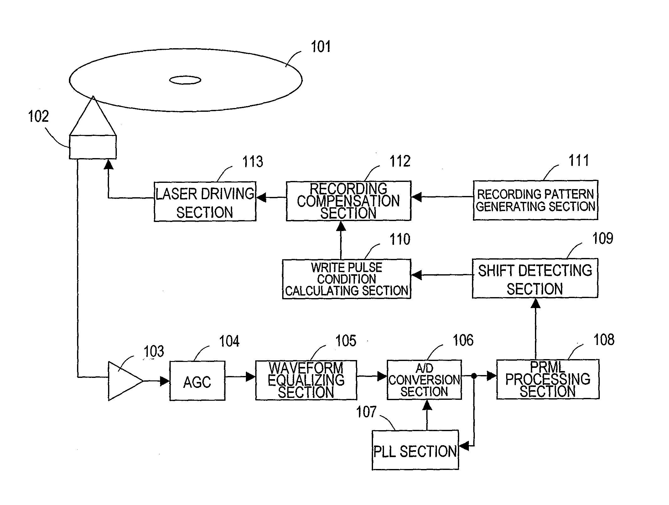
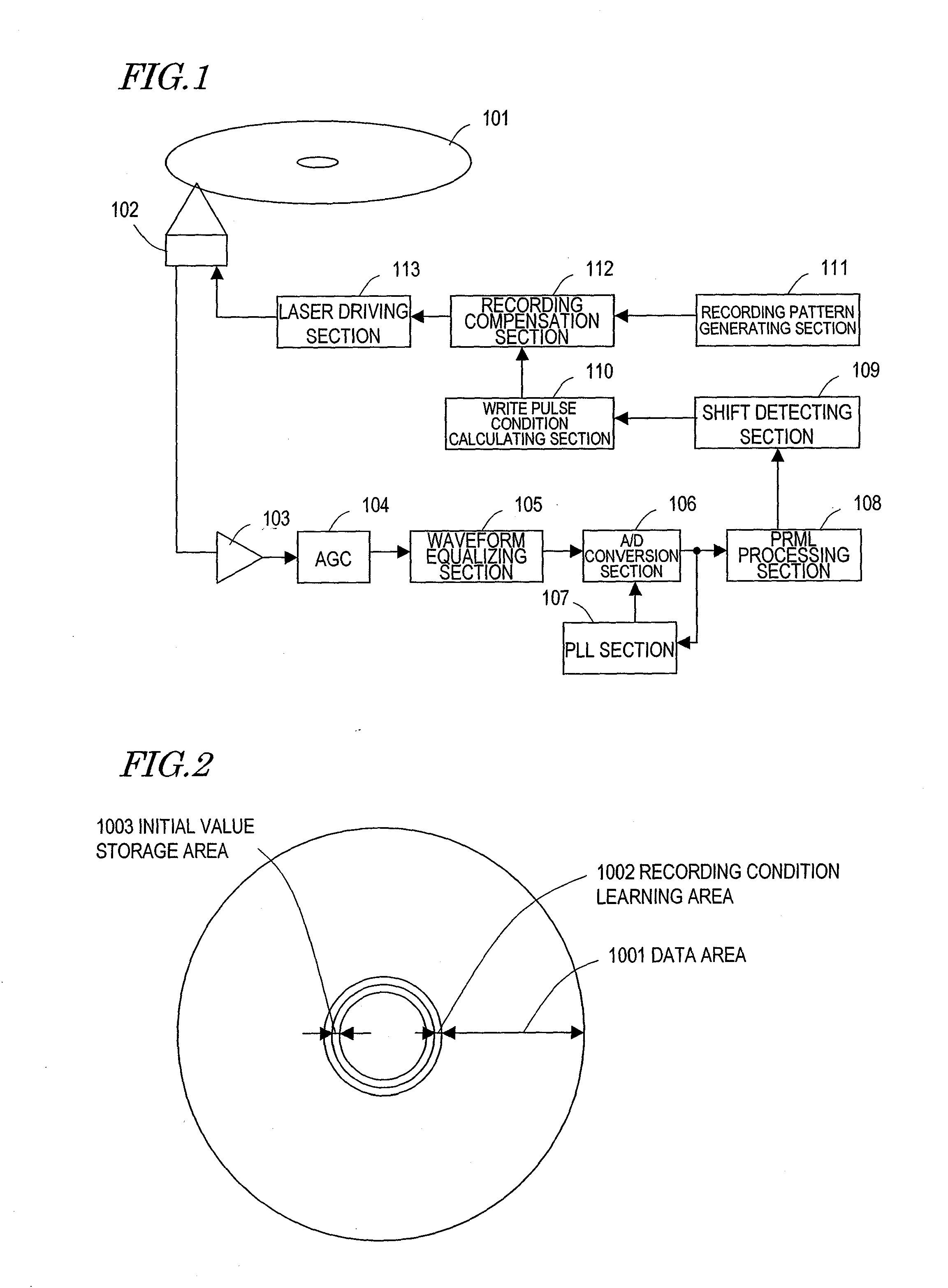
[0077]Hereinafter, embodiments of the present invention are described with reference to the accompanying drawings. The embodiments are described with examples of a write-once, phase-change type optical disc medium (especially, BD-R (write-once Blu-ray Disc)) used as a recording medium. Note that this does not mean that the recording medium is limited to any particular type. The type of the recording medium is nonlimiting so long as it is of such a type that information is recorded by injecting energy into the recording medium to form marks or pits which have different physical properties from unrecorded part. For example, the techniques described herein are commonly applicable to rewritable optical disc media (e.g., BD-REs (rewritable Blu-ray Discs)). The techniques described herein are also commonly applicable to heat-mode recording on an inorganic resist coating, as is the case with a master-manufacturing exposure apparatus called a PTM (Phase Transition Mastering) apparatus that ...


PUM


Abstract

An optical recording method for recording information by irradiating an optical disc medium with a modulated write pulse train of laser light variable over a plurality of power levels such that a plurality of marks are formed on the optical disc medium, edge positions of each of the marks and a space between adjacent two of the marks being utilized for recording of the information. The optical recording method includes the steps of: encoding record data to generate encoded data which is a combination of marks and spaces; classifying the encoded data according to a combination of a mark length of the mark, a space length of a first space that immediately precedes the mark, and a space length of a second space that immediately succeeds the mark; generating a write pulse train for forming the mark, in which at least one of a leading end edge position, a trailing end edge position and a pulse width of the write pulse train is changed according to a classification result; and irradiating the optical disc medium with the write pulse train generated to form the plurality of marks on the optical disc medium.

Description

[0001]This application claims priority under 35 U.S.C. §119 to U.S. Provisional Application Nos. 61 / 120,880 filed Dec. 9, 2008 and 61 / 157,582 filed Mar. 5 2009, both of which are incorporated herein by reference in its entirety.BACKGROUND OF THE INVENTION[0002]1. Field of the Invention[0003]The present invention relates to an optical recording method, an apparatus for manufacturing a master through an exposure process (master-manufacturing exposure apparatus), an optical information recording medium, and a reproduction method, which utilize maximum likelihood decoding, such as PRML, an optical recording apparatus. More particularly, the present invention relates to a technique of writing under the optimum recording conditions by making adaptive recording compensation at least according to the space lengths of spaces preceding and succeeding an interested mark, for the purpose of decreasing optical intersymbol interference or thermal interference which is caused in recording of or re...

Claims


Application Information

Patent Timeline
IPC IPC(8): G11B7/0045
CPCG11B7/00456G11B2007/0013G11B7/261G11B7/0062
Inventor NAKAMURA, ATSUSHIKOBAYASHI, ISAOFURUMIYA, SHIGERU
Owner PANASONIC CORP
Why Eureka
Try Eureka