Processes and methods for low energy carbon dioxide capture

a carbon dioxide and low energy technology, applied in the field of low energy carbon dioxide capture processes and methods, can solve the problems of not being superior to conventional amine technology at typical regeneration pressure and temperature, and the reaction kinetics are significantly slower than those of primary amine-based

Inactive Publication Date: 2015-08-20
CO2 SOLUTION
View PDF2 Cites 13 Cited by
  • Summary
  • Abstract
  • Description
  • Claims
  • Application Information

AI Technical Summary

Problems solved by technology

However, these alternative capture solutions suffer from two significant drawbacks in that the reaction kinetics are significantly slower than those of primary amine-based solutions, and in that the total specific heat duty (thermal regeneration energy input per mole of CO2 captured) is not superior to conventional amine technology at typical regeneration pressures and temperatures.
Several researchers have explored adding chemical additives such as piperazine or arsenate to accelerate absorption in potassium carbonate solutions, but in doing so the blended solution becomes less environmentally acceptable, more prone to oxidation breakdown, and increases the potential to emit hazardous air pollutants and volatile organic compounds—drawbacks that are commonly associated with traditional, high heat of reaction primary amine solvents.
Since higher temperature heat sources are more valuable to industrial operations, regeneration at high temperatures can negatively impact the cost of CO2 capture.
Conversely, low-heat-of-reaction solvents generally exhibit minimum regeneration energy at lower temperatures; however, regeneration performance may be limited by unfavorable reaction kinetics.

Method used


Image

  • Processes and methods for low energy carbon dioxide capture
  • Processes and methods for low energy carbon dioxide capture
  • Processes and methods for low energy carbon dioxide capture

Examples


example 1

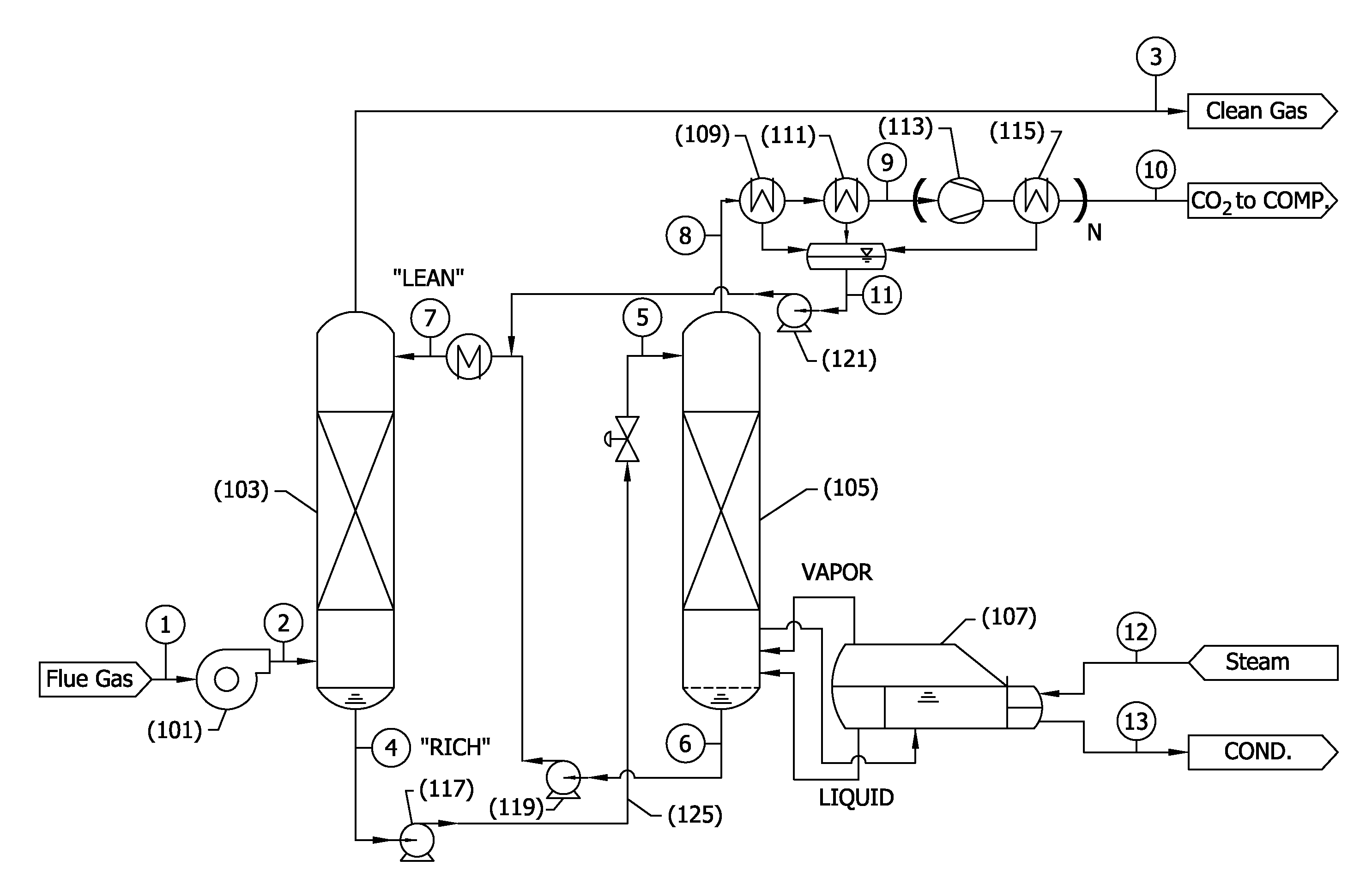
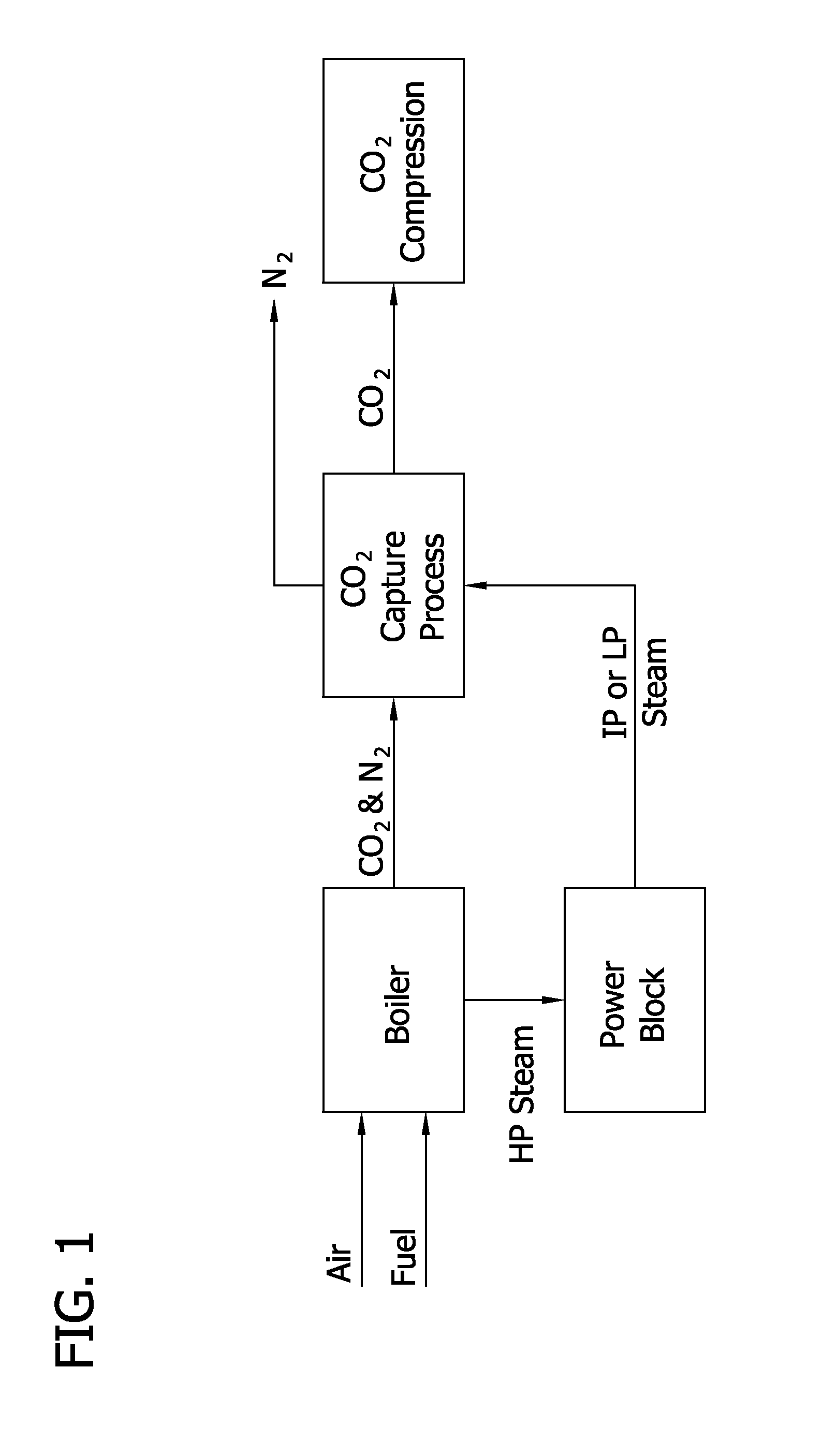
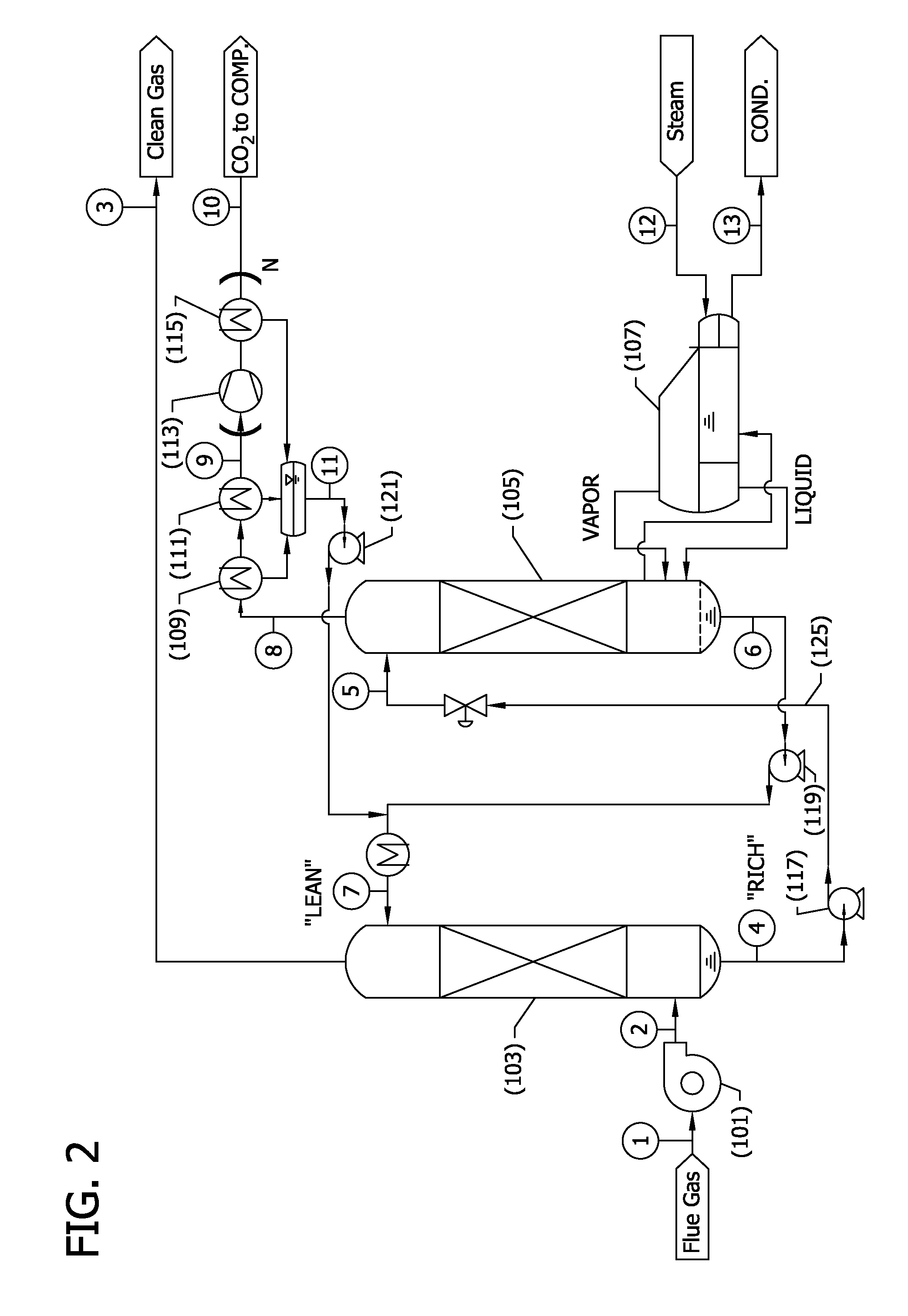
[0123]Preliminary modeling was conducted for a CO2 capture process corresponding to the flow sheet depicted in FIG. 2 integrated into a coal combustion, supercritical steam, power plant as shown in FIG. 3, and as described in detail above.

[0124]Generally, FIG. 3 illustrates how a CO2 capture system as described herein might be integrated into a coal fired steam power plant. Unique features of the integration are disclosed to minimize parasitic power and minimize capital cost in a retrofit application where regeneration steam is collected at 201 entirely from the bottom of one side of the low-pressure steam turbine doublet—in contrast to the conventional split of steam flow at the inlet of the low pressure turbine 203. The figure shows the main plant condenser 207 located immediately after the reboiler 205 to aid in drafting low pressure steam through the reboiler steam tubes. As an alternative, a separate condenser could have been located in close proximity to the reboiler. Addition...

example 2

[0136]The model data presented in FIG. 6 illustrate the significant changes in saturated steam-to-power efficiency as a function of reboiler temperature. The data markers on the plot illustrate potential for 70% reduction in parasitic power for a 60° C. reboiler (70° C. steam) compared to a 150° C. reboiler (160° C. steam), for the same reboiler heat duty. Moreover, to the extent that reboiler heat duty can also be lowered considering a preferred solvent selection, as in this invention, then the parasitic power will be further reduced. The steam to power efficiency is approximated by 90% of ideal Carnot heat cycle efficiency, assumes a minimum reference temperature of 40° C. (313 K), and assumes a steam saturation temperature that is 10° C. above the reboiler temperature.

example 3

[0137]Process modeling and cost estimation for CO2 capture from flue gas generated by a supercritical steam, pulverized coal, power plant was performed to evaluate the benefits of the advanced process flow sheet disclosed herein with 20% w / w K2CO3 and 34% w / w KDMG compared to 30% w / w MEA. To separate the roles of solvent and flow sheet in reducing equivalent work the corresponding cost of CO2 capture, the energy and cost performances were compared to the use of a conventional flow sheet with ambient pressure regeneration and with catalyst present only in the absorber, a conventional flow sheet with vacuum stripping and catalyst present only in the absorber, and the advanced flow sheet disclosed in FIG. 2 and described in detail above, which features a biocatalyst circulating throughout the entire liquid solvent loop.

[0138]FIG. 7 presents the equivalent work that resulted from detailed energy balance modeling of various process flow sheets and solvents cases defined in the list below...


PUM

PropertyMeasurementUnit
temperatureaaaaaaaaaa

Abstract

The present invention generally relates to processes and methods for the capture of carbon dioxide from gases that are produced by various industrial processes including the capture of CO2 from flue gases after the combustion of carbon-based fuels.

Description

CROSS-REFERENCE TO RELATED APPLICATIONS[0001]This application claims the benefit of U.S. Provisional Application Ser. No. 61 / 941,158 which was filed Feb. 18, 2014. The entire content of this application is incorporated herein by reference.FIELD OF THE INVENTION[0002]The present invention generally relates to processes and methods for the capture of carbon dioxide from gases that are produced by various industrial processes including the capture of CO2 from flue gases after the combustion of carbon-based fuels.BACKGROUND OF THE INVENTION[0003]Coal is the largest source of energy for the generation of electricity worldwide. World coal consumption is expected to increase to reach 9.05 billion tonnes by 2030. The flue gas generated by coal-fired power plants is the largest worldwide anthropogenic sources of carbon dioxide, and the capture and sequestration of carbon dioxide produced in the combustion of coal represents an important opportunity to reduce the electric grid's GHG footprint...

Claims


Application Information

Patent Timeline
Patent Type & Authority Applications(United States)
IPC IPC(8): B01D53/84B01D53/62B01D53/96
CPCB01D53/62B01D53/84B01D53/96B01D2251/606B01D2252/20494B01D2255/804B01D2257/504Y02A50/20Y02C20/40
Inventor REARDON, JOHNSHAFFER, ALEXANDERBUCHOLZ, TRACYZAKS, ALEKSEY
Owner CO2 SOLUTION
Why Eureka
Try Eureka