
Graphene enhanced elastomeric stator

a technology of elastomeric stator and graphene, which is applied in the direction of liquid fuel engines, machines/engines, rotary piston liquid engines, etc., can solve the problems of inability to detect grain boundaries, inability to meet the requirements of elastomeric stator, so as to increase the interaction of polymer and filler, improve the effect of elastomeric stator and structural enhancemen

Active Publication Date: 2015-08-20
REMY TECHNOLOGIES LLC
View PDF4 Cites 15 Cited by
  • Summary
  • Abstract
  • Description
  • Claims
  • Application Information

AI Technical Summary

Benefits of technology

The present invention is about a method of making a graphene enhanced elastomeric stator assembly. The process involves adding graphene particles, cross-linkable polymers, coupling agents, and reducing filler material to enhance the structure and useful life of the stator. The graphene particles improve the interactions between the polymer and filler, increasing the stator's useful life. The use of cross-linkable plasticizers further strengthens the structure of the compound and enables the material to flow through a mold over a long distance. The plasticizer also prevents the extraction of the plasticizer and combats damage to the stator caused by heat build-up. Overall, the invention results in a stronger, more durable, and efficient elastomeric stator.

Problems solved by technology

A challenge to producing a high power, high torque, and high speed power section stator, is that manufacturing equipment and cost effective tooling materials require a low viscosity uncured elastomer compound that is capable of flowing through a tight mould cavity over a long distance while maintaining its uncured state.
If a compound is too viscous it cannot flow the appropriate distance to fill the mould.
Separately formed matrices create undetectable grain boundaries in the elastomer product which will often fail prematurely due to significant losses in tear resistance, losses in modulus, and or friction points internally that facilitate rapid physical deterioration of the surrounding elastomer matrix.
Although such combinations are favorable for manufacturability, the resulting recipe negatively impacts the final cured state properties of the elastomer, often making the formulation softer and less dynamically stable.
For example, plasticizer oil may be used to decrease viscosity during manufacturing but, in the finished product, it has a tendency to leach out of the elastomer at high temperatures when exposed to diverse drilling fluids, which can cause shrinkage in the product or de-bonding of the rubber to metal bonding agents, and also facilitate the absorption of chemicals from drilling fluid.
This means their potential in power sections stator compounds requires such low loadings (to maintain manufacturability) that the cured state physical properties are not attainable at an affordable, reproducible level of satisfaction.
Further, though the helical metal rotors of progressive cavity motors are heat tolerant, abrasion resistant, and have generally long useful lives, the stators of progressive cavity motors are far less reliable and often fail, need servicing, or replacement before their rotor counterparts.
The carbon black reinforced liner of stators tends to wear down when exposed to abrasive materials, can develop leaks between cavities.
When exposed to harsh temperatures a rubber compound will soften and can result in seal lines being less capable of handling high differential pressure which can result in a loss in torque.
High temperatures can also cause the rubber in a liner to thermally expand, which can lead to overheating.
Long term exposure to such conditions can cause the rubber to become brittle and lead to low tear resistance.
Failures can occur in the form of a section worn down by abrasion leaking and not providing proper sealing pressure against the metal rotor lobes; a physical tear of the inner lining can also occur and cause an immediate shutdown of the entire system.
For example, when the stator fails, the rotor can pump torn rubber pieces through cavities and damage other components of the downhole assembly or stop rotating all together.
Exposure to certain chemicals or downhole fluids can additionally cause degradation of the stator inner walls.
Harsh drilling fluids can be absorbed into the rubber liner, causing swelling which leads to the rubber liner overheating in operation.

Method used


Image

  • Graphene enhanced elastomeric stator
  • Graphene enhanced elastomeric stator
  • Graphene enhanced elastomeric stator

Examples


Embodiment Construction

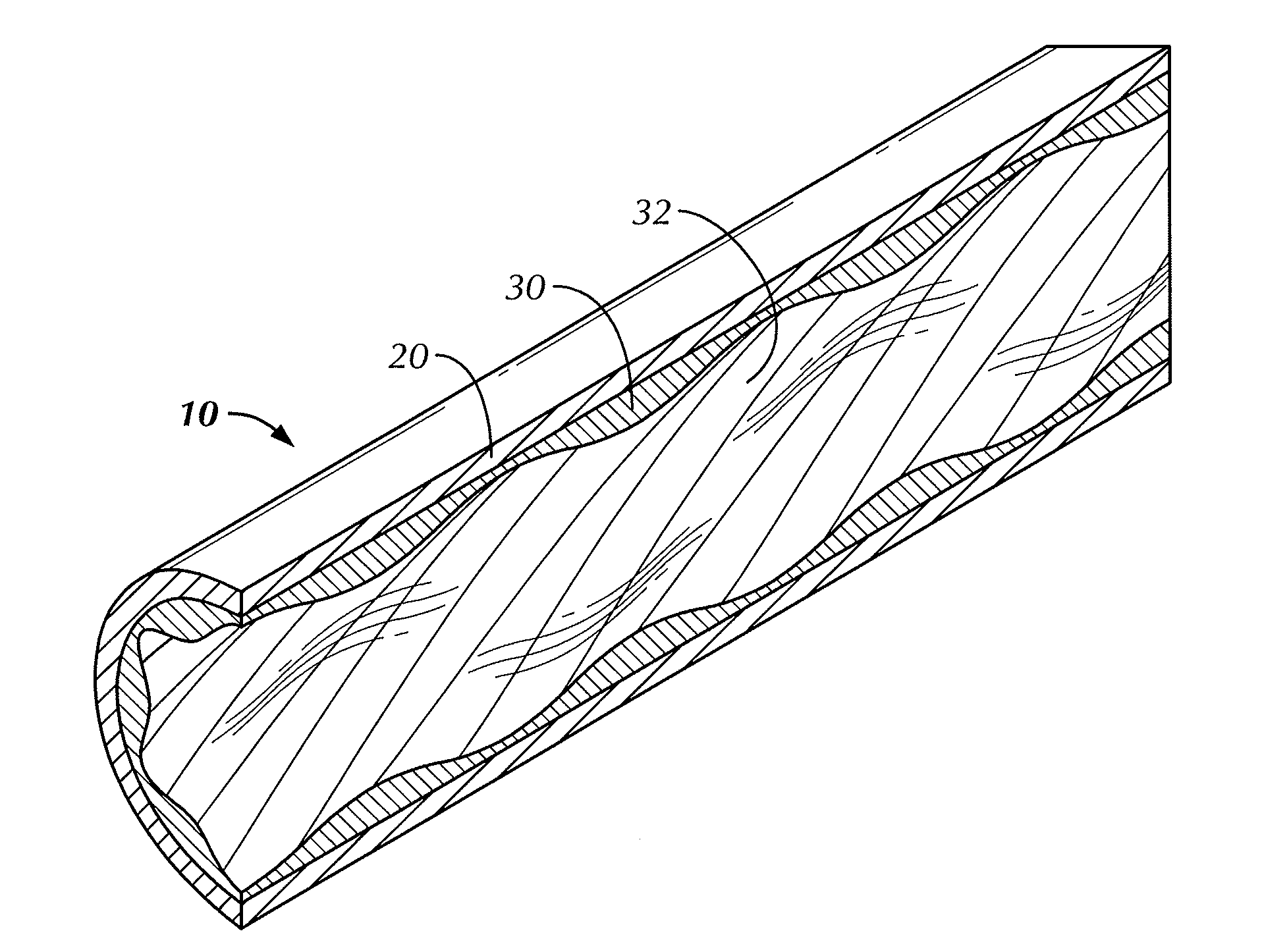
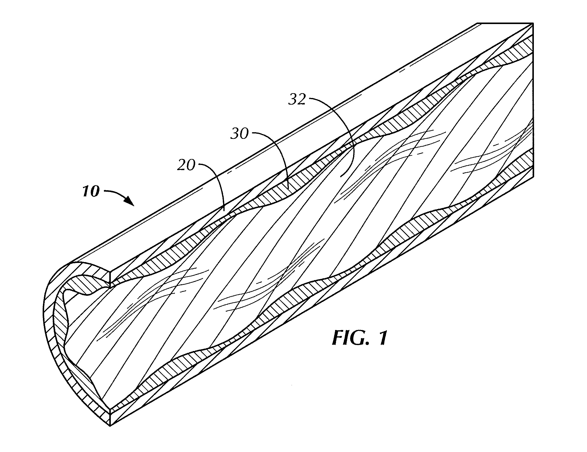
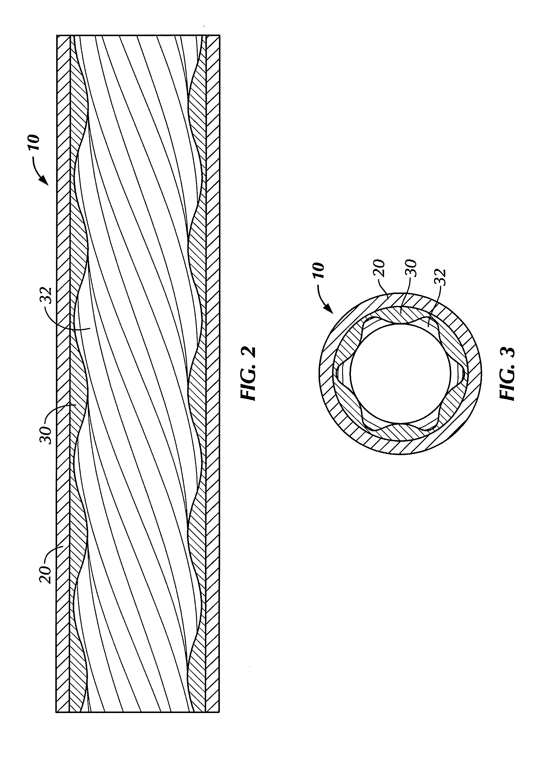
[0029]Elastomeric stators in progressive cavity motors are often configured with hard metal tubular exterior sleeves and inner elastomeric stator liners that are typically formed by injection molding the liner over a mould mandrel. FIGS. 1-3 depict multiple views of an embodiment of an elastomeric stator assembly 10. Many variations exist regarding the shapes, sizes, and dimensions of elastomeric stators and FIGS. 1-3 merely illustrate an exemplary embodiment of an elastomeric stator assembly as can be configured with any of the various graphene enhanced elastomeric stator compound embodiments described herein or any combination of the multiple embodiments as described herein.

[0030]Referring to FIGS. 1-3, in an embodiment, a graphene enhanced elastomeric stator assembly 10 is shown having a metal outer tubular surface 20 and a graphene enhanced elastomeric stator inner liner 30 that connects to the outer tubular surface 20. The elastomeric stator liner inner walls 32 can be formed i...


PUM

PropertyMeasurementUnit
elastomericaaaaaaaaaa
thicknessaaaaaaaaaa
Mooney viscosityaaaaaaaaaa

Abstract

An enhanced elastomeric stator assembly and method of making the same is disclosed. The elastomeric stator may be structurally, thermally, and / or chemically enhanced through the incorporation of graphene particles, cross-linkable polymers, coupling agents that extend cross-links, and by the reduction of filler material. The graphene particles can be incorporated in functionalized or non-functionalized form or in a combination thereof, the functionalized graphene increasing the number of cross-links in the overall structure, thereby enhancing the structural robustness of the elastomeric stator. The compound can be formulated to have a relatively low viscosity and other characteristics that allow the material to flow through a mould cavity.

Description

BACKGROUND[0001]1. Field of the Invention[0002]The present invention relates to improved elastomeric stator assemblies.[0003]2. Description of the Related Art[0004]Progressive cavity pumps having elastomeric stator assemblies have been used in drilling operations for some time. In downhole drilling operations, progressive cavity motors pump fluids by spinning a rotor within a stator assembly. In particular, power sections for mud motors have seen extensive use of progressive cavity pumps in the inverse application where drilling fluid is used to turn a rotor within a stator. Often, progressive cavity motors are configured with helical metal lobed rotors that turn within elastomeric stators consisting of rubber with high carbon black filler content. The high carbon black rubber provides a suitable yet cost efficient material having some compressive modulus and abrasion resistance properties. As the metal lobes of the rotors press against the elastomeric stator inner walls, a sealing ...

Claims


Application Information

Patent Timeline
Patent Type & Authority Applications(United States)
IPC IPC(8): F04C2/107C08K9/00C08K3/04F04C13/00E21B4/02
CPCF05C2203/0808F05C2251/042F05C2253/04C08K5/14C08K9/04C08K3/042F04C2/1075F04C13/008E21B4/02C08K3/04F05C2225/02F05C2251/02F05C2231/00Y10T29/49242C08L9/02C08L15/005C01B32/194B82B1/003B82B3/0028B82Y30/00F01C1/107F04C2/107
Inventor SICILIAN, JOSHUA ALAN
Owner REMY TECHNOLOGIES LLC
Learn More