Lens Antenna, Method for Manufacturing and Using such an Antenna, and Antenna System

a technology of lens antenna and antenna system, applied in the field of lens antenna, can solve the problems interference and signal disruption, and difficulty in separating transmission media from sources of electromagnetic and radio frequency interference, and in some instances impossibl

Active Publication Date: 2015-08-20
THE ANTENNA COMPANY INT
View PDF1 Cites 33 Cited by
  • Summary
  • Abstract
  • Description
  • Claims
  • Application Information

AI Technical Summary

Problems solved by technology

The primary sources of interference that effect wireless communication systems are electromagnetic in nature and can result in the magnetic and radio frequency disruption or intermittent failure of electronic, communication and information systems.
Wireless communication data links utilize free-space propagation and are subject to interference and signal disruption from a broad spectrum of sources.
This represents one of the most significant challenges for designers of these systems, whereas it is difficult, and in some instances impossible, to isolate the transmission media from sources of electromagnetic and radio frequency interference.
The increased reliance on wireless networks data networks and wireless network segments introduces an additional vulnerability in relation to network operation and survivability.
These wireless systems are subject to increased band congestion interference and the possibility introduction of an intentional interference source.
The ability to transmit directed energy to critical wireless nodes can result in the temporary or permanent disruption of network connectivity and services.
However, compact and low-profile antennas are highly important for such applications, for either mechanical reasons or due to the miniaturization of electronic equipment in general.
It is well known that, as the size of the antenna is reduced, the efficiency tends to degrade and the bandwidth becomes narrower.
So, the conflicting nature of the requirements of high performance and compact size makes the design of these antennas very challenging.
In addition, the interaction of the antenna with its complex environment also affects its performance.
Furthermore, in mobile station applications, even multiple different antenna probes can be used in a limited available space to provide multiband operation.
However, application of such a separate reflective element will commonly affect the efficiency of the antenna.
However, usage of many antennas is usually limited by the volume and cost constraints of the applications.
The adopted multiple feeding mechanism, allowing for an easy wide-range tuneability of the antenna performance, has to be optimized in such a way as to minimize the level of spurious electromagnetic coupling between the antenna ports (probes), potentially resulting in a degradation of the device performance.
Despite of the fact that the proposed antennas are extremely simple to construct, easily machinable and thus cheap, they surprisingly considerably outperform antennas currently used in wireless communications in terms of operational bandwidth, maximum gain, and radiation pattern agility.
The presence of sharp edges does necessarily not reduce the radiation efficiency of the preferred antenna.
If the power supply and ground wires have significant resistance, the voltage drop across them can create noise voltage pulses in the ground wires, which are applied to other parts of the circuit.
When the antennas are closely placed, the electromagnetic waves of different antennas interfere with each other resulting in signal loss.
In MIMO systems, a major problem faced by the designers is mutual coupling, which arises mainly due to the electromagnetic interactions between the antennas in the array.
This problem mainly occurs due to the small spacing between the antennas in the array.

Method used


Image

  • Lens Antenna, Method for Manufacturing and Using such an Antenna, and Antenna System
  • Lens Antenna, Method for Manufacturing and Using such an Antenna, and Antenna System
  • Lens Antenna, Method for Manufacturing and Using such an Antenna, and Antenna System

Examples


Embodiment Construction

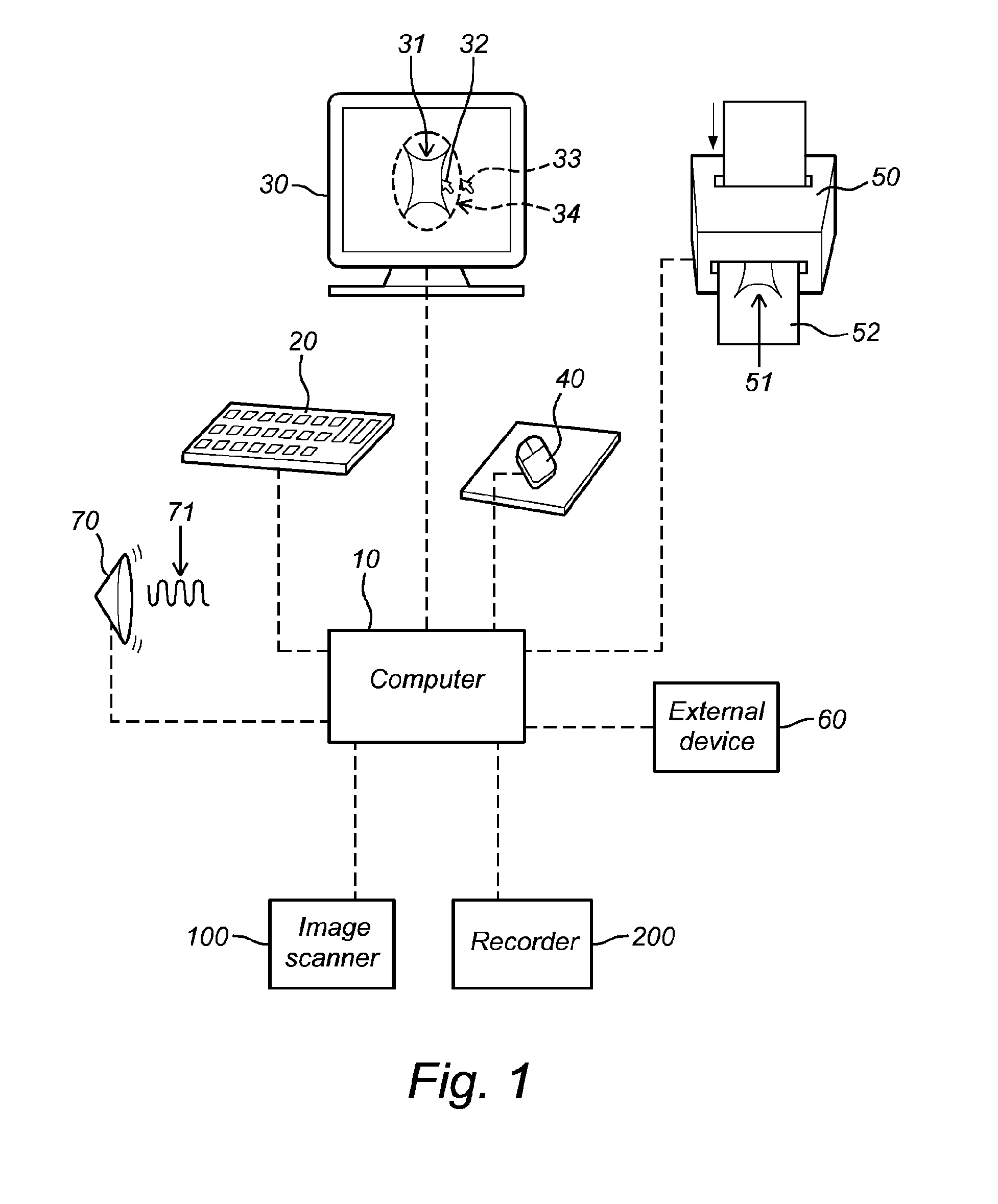
[0075]According to the first aspect, for illustrative purposes with reference to FIG. 1, which is also incorporated in U.S. Pat. No. 7,620,527 as FIG. 16, shapes or waves of a ground plane and / or a lens of an antenna according to the invention, can be “synthesized” by the application of the following exemplary basic steps:

[0076]In a first step, a choice of parameters is made (e.g., by either inputting values into the computer 10, i.e., via a keyboard 20, a touch screen, a mouse-pointer, a voice recognition device or other input device or the like, or by having the computer 10 designate values), and the computer 10 is used to synthesize a selected super-shape based on the choice of parameters.

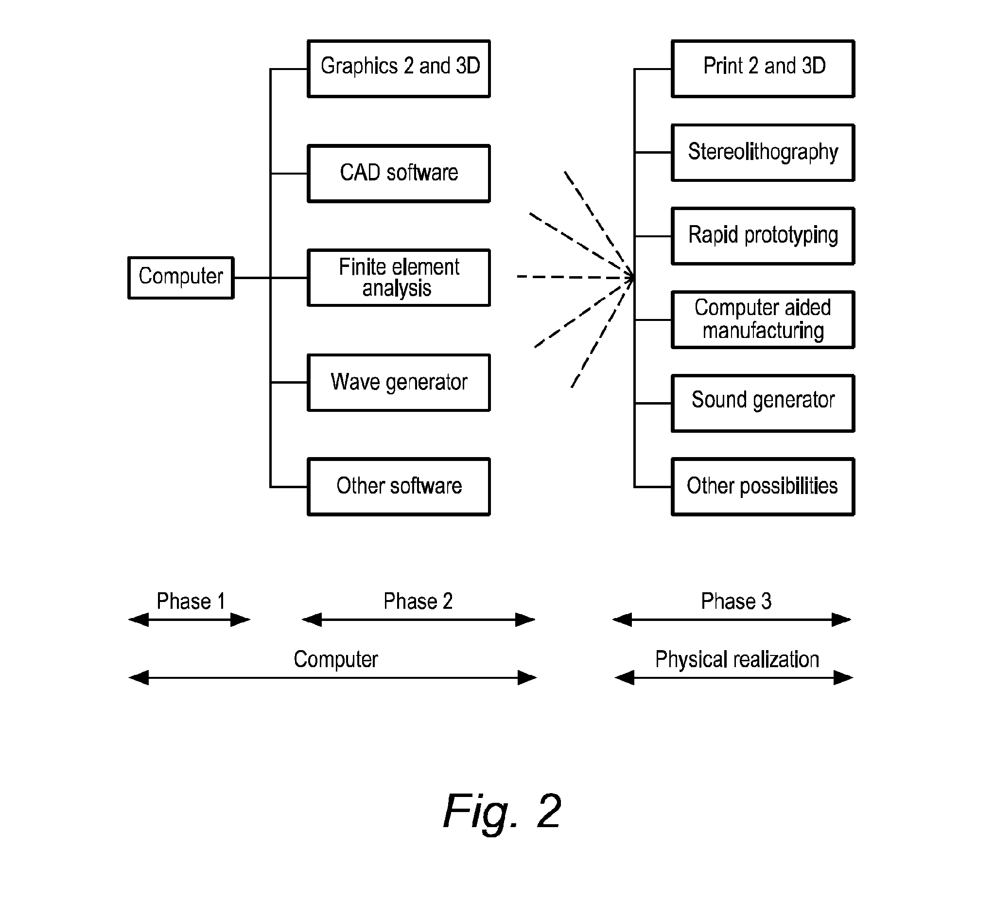
[0077]In a second optional step, the super-formula can be used to adapt the selected shapes, to calculate optimization, etc. This step can include use of: graphics programs (e.g., 2D, 3D, etc.); CAD software; finite element analysis programs; wave generation programs; or other software.

[0078]In ...


PUM

PropertyMeasurementUnit
lengthaaaaaaaaaa
lengthaaaaaaaaaa
lengthaaaaaaaaaa

Abstract

The invention relates to a lens antenna. The invention also relates to an antenna system for transmitting and receiving electromagnetic signals comprising at least one antenna according to the invention. The invention further relates to a method of manufacturing an antenna according to the invention. The invention moreover relates to a method for use in wireless communications by using an antenna according to the invention. The invention additionally relates to a RF transceiver of a wireless communications device comprising at least one antenna according to the invention. The invention further relates to an electronic device comprising an RF transceiver according to the invention.

Description

INTRODUCTION[0001]The invention relates to a lens antenna. The invention also relates to an antenna system for transmitting and receiving electromagnetic signals comprising at least one antenna according to the invention. The invention further relates to a method of manufacturing an antenna according to the invention. The invention moreover relates to a method for use in wireless communications by using an antenna according to the invention. The invention additionally relates to an RF transceiver of a wireless communications device comprising at least one antenna according to the invention. The invention further relates to an electronic device comprising an RF transceiver according to the invention.[0002]The increasing demand for data communications and connectivity has resulted in the development of innovative methods to satisfy current and emerging communication requirements. The path on which data travels from its source to its destination is described as a communications link. T...

Claims


Application Information

Patent Timeline
Patent Type & Authority Applications(United States)
IPC IPC(8): H01Q19/06H01Q5/45H01Q1/48H01Q15/08H01Q5/35
CPCH01Q19/062H01Q1/48H01Q5/45H01Q15/08H01Q9/0485H01Q19/08H01Q5/35Y10T29/49016H01Q19/06Y10T29/49018H04B7/12
Inventor CARATELLI, DIEGOGIELIS, JOHAN LEO ALFONS
Owner THE ANTENNA COMPANY INT
Why Eureka
Try Eureka