
Malfunction-Determining Device for Exhaust Gas Purifying Device and Malfunction-Determining Method for Exhaust Gas Purifying Device

Active Publication Date: 2015-08-27
KOMATSU LTD
View PDF10 Cites 12 Cited by
  • Summary
  • Abstract
  • Description
  • Claims
  • Application Information

AI Technical Summary

Benefits of technology

The patent text describes a method for identifying malfunctions in pressure sensors used in engines and machines. It explains that malfunctions are usually caused by the pressure sensor being unable to properly introduce pressure due to freezing of water in a duct. The text describes a method to eliminate the malfunction by allowing the pressure to gradually unfroze as the temperature increases. The technical effect of this method is that it allows the vehicle or machine to continue operating even when the pressure measuring device is determined to be frozen, thereby maintaining a favorable operation rate.

Problems solved by technology

However, it has been found that a malfunction of a pressure sensor at the start-up of an engine at a low temperature is usually not attributed to a failure in the pressure sensor itself but to improper introduction of pressure into the pressure sensor due to freezing of condensation water in a pressure-introducing duct.
Therefore, even though it is highly possible that the malfunction is eliminated by continuing the ongoing operation, a serviceperson is called and a vehicle or a machine is stopped for inspection, which results in lowering the operation rate of the vehicle or machine.

Method used


Image

  • Malfunction-Determining Device for Exhaust Gas Purifying Device and Malfunction-Determining Method for Exhaust Gas Purifying Device
  • Malfunction-Determining Device for Exhaust Gas Purifying Device and Malfunction-Determining Method for Exhaust Gas Purifying Device
  • Malfunction-Determining Device for Exhaust Gas Purifying Device and Malfunction-Determining Method for Exhaust Gas Purifying Device

Examples


Embodiment Construction

)

[0035]An exemplary embodiment of the invention will be described below with reference to the attached drawings.

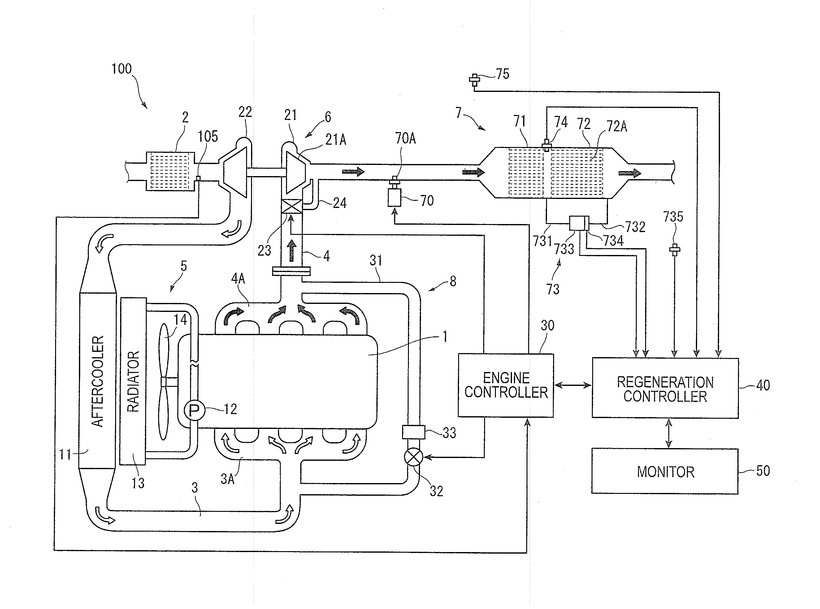
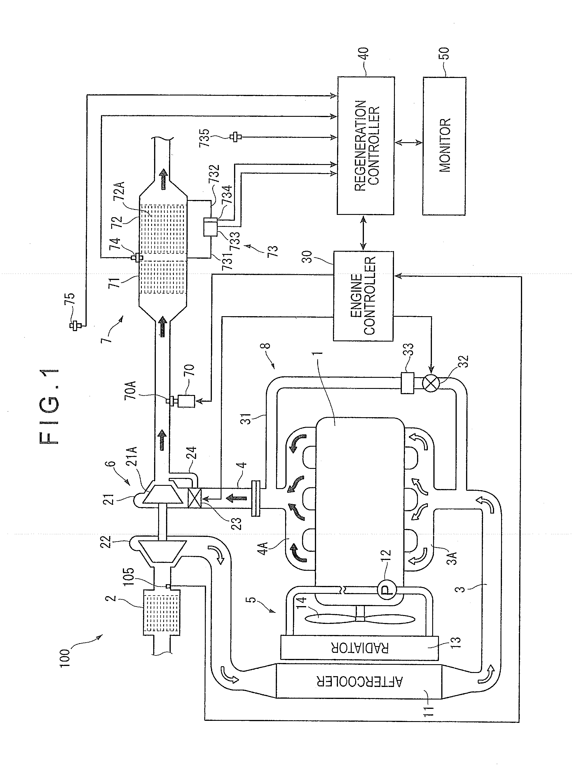
[0036]FIG. 1 schematically shows an arrangement of a diesel engine 100 as an internal combustion engine including a malfunction-determining device of an exhaust gas purifying device according to the exemplary embodiment of the invention.

Schematic Description on Overall Arrangement of Diesel Engine

[0037]As shown in FIG. 1, the diesel engine 100 includes: an engine body 1 in which a plurality of combustion chambers are provided; an air cleaner 2 through which intake air is filtered to prevent foreign substances such as dust from entering the combustion chambers; an intake pipe 3 through which the intake air is supplied to the combustion chambers in the engine body 1; an exhaust pipe 4 through which exhaust gas is discharged from the combustion chambers in the engine body 1; a cooling system 5; a turbocharger 6; an exhaust gas purifying device 7; an exhaust-gas-recirculation ...


PUM


Abstract

A malfunction-determining device for an exhaust gas purifying device, which includes a filter device and a pressure measuring device, includes a usability determiner being configured to determine whether or not the pressure measuring device is usable based on a pressure measured by the pressure measuring device and an exhaust gas flow rate, a frozen-state determiner being configured to determine whether or not the pressure measuring device is frozen, and a malfunction determiner being configured to determine that the pressure measuring device has a malfunction when the usability determiner determines that the pressure measuring device is unusable and the frozen-state determiner determines that the pressure measuring device is not frozen.

Description

TECHNICAL FIELD[0001]The present invention relates to a malfunction-determining device for an exhaust gas purifying device and a malfunction-determining method for an exhaust gas purifying device.BACKGROUND ART[0002]Nowadays, vehicles / machines equipped with an internal combustion engine (e.g., a diesel engine) such as construction machines (e.g., hydraulic excavator and wheel loader), haulage vehicles (e.g., bus, freight truck, dump truck and on-road truck), and fixed power generators are provided with an exhaust gas purifying device in which particulate matter (PM) in exhaust gas from the internal combustion engine is removed through a diesel particulate filter (DPF). The exhaust gas purifying device is equipped with a pressure sensor (differential-pressure sensor) that detects a differential pressure in a filter used as the DPF between an inlet-side pressure and an outlet-side pressure of exhaust gas. Based on the differential pressure detected by the pressure sensor, the amount o...

Claims


Application Information

Patent Timeline
IPC IPC(8): F01N11/00G01M15/10
CPCG01M15/106F01N11/002F02D41/029F02D41/1445F02D41/148F02D41/222F02D2200/0812Y02T10/40B01D53/92F01N3/00F01N3/021F01N11/00G01M13/005G01N7/00
Inventor SAITOU, SHINICHINAGASAKA, SHOUHEIKIMURA, MITSUYOSHINAKANO, KEN
Owner KOMATSU LTD
Learn More