Solar photovoltaic facility
- Summary
- Abstract
- Description
- Claims
- Application Information
AI Technical Summary
Benefits of technology
Problems solved by technology
Method used
Image
Examples
first embodiment
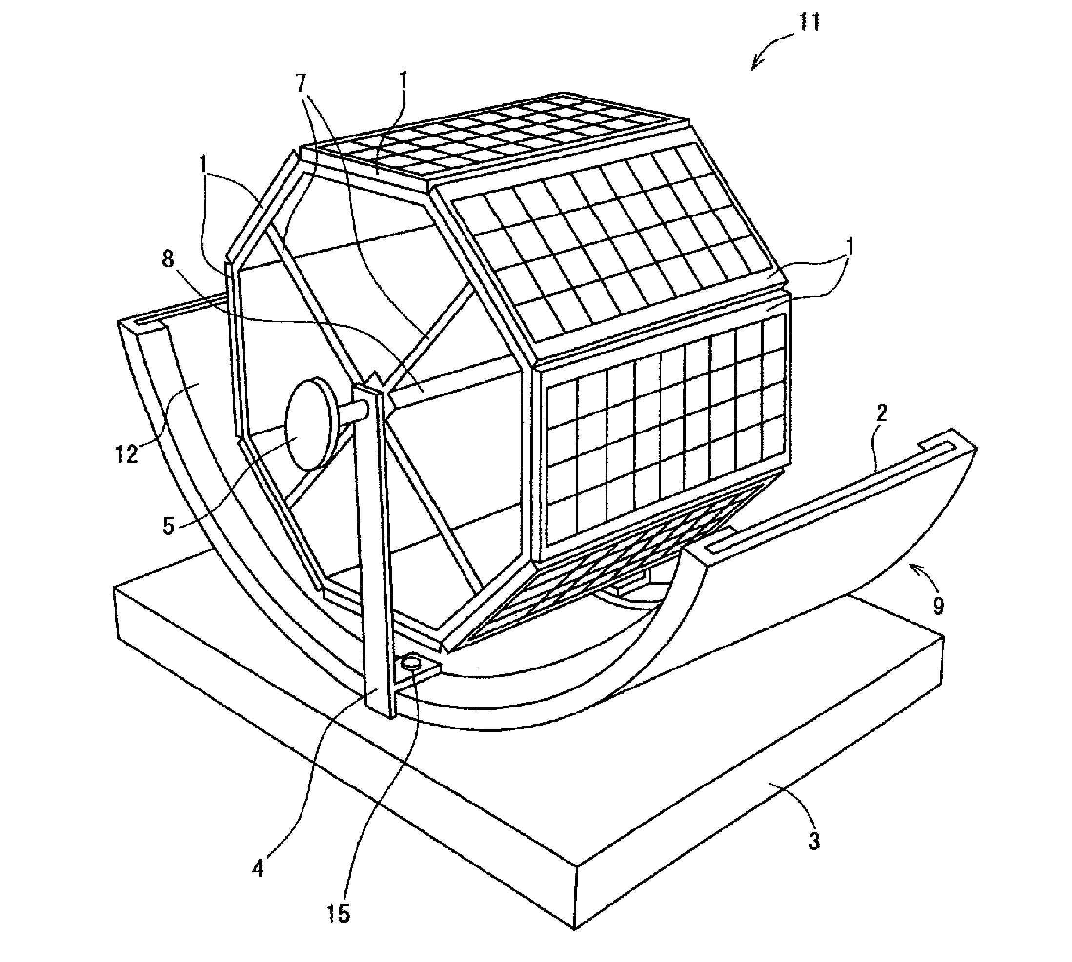
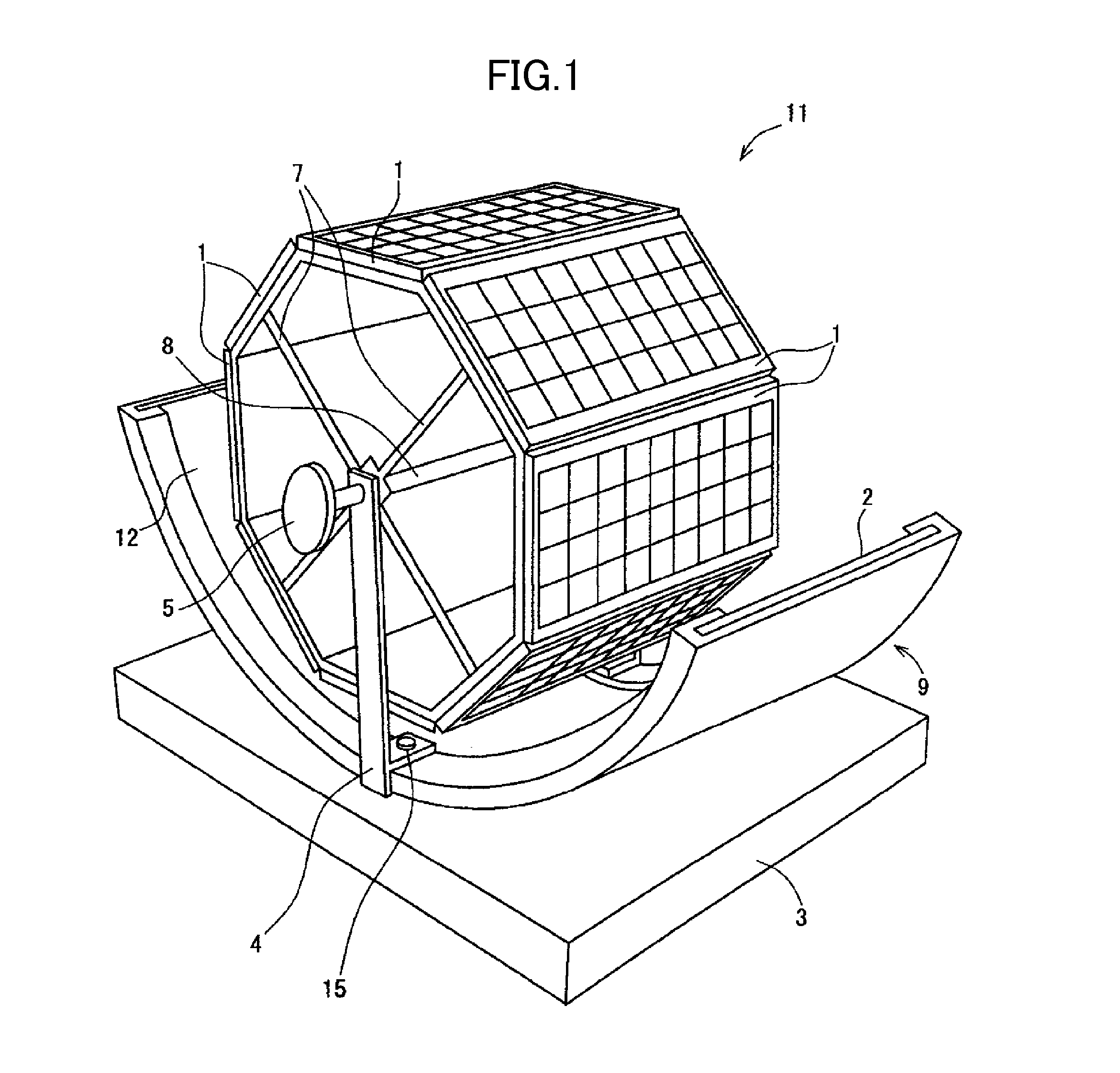
[0036]FIG. 1 shows a solar power generation apparatus according to the present invention, and the solar power generation apparatus includes solar cell panels 1, a curved mirror 2, a rotation shaft 8, a handle 5, a base 3, and struts 4 vertically erected from the base 3.
[0037]The solar cell panel 1 is in a panel shape where plural solar cells which are power devices directly converting light energy into power using a photovoltaic effect are connected in series and in parallel and thereby necessary voltage and current can be obtained. A solar cell panel body 11 is obtained by disposing the solar cell panels 1 in an octagonal prism shape. The solar cell panel body 11 may be obtained by disposing the solar cell panels 1 in a polygonal prism shape or a cylindrical shape other than the octagonal prism shape.
[0038]The curved mirror 2 is a reflection plate which reflects the sunlight using a reflection surface 12, and the reflection surface 12 is formed to be concaved. A cross-section of th...
second embodiment
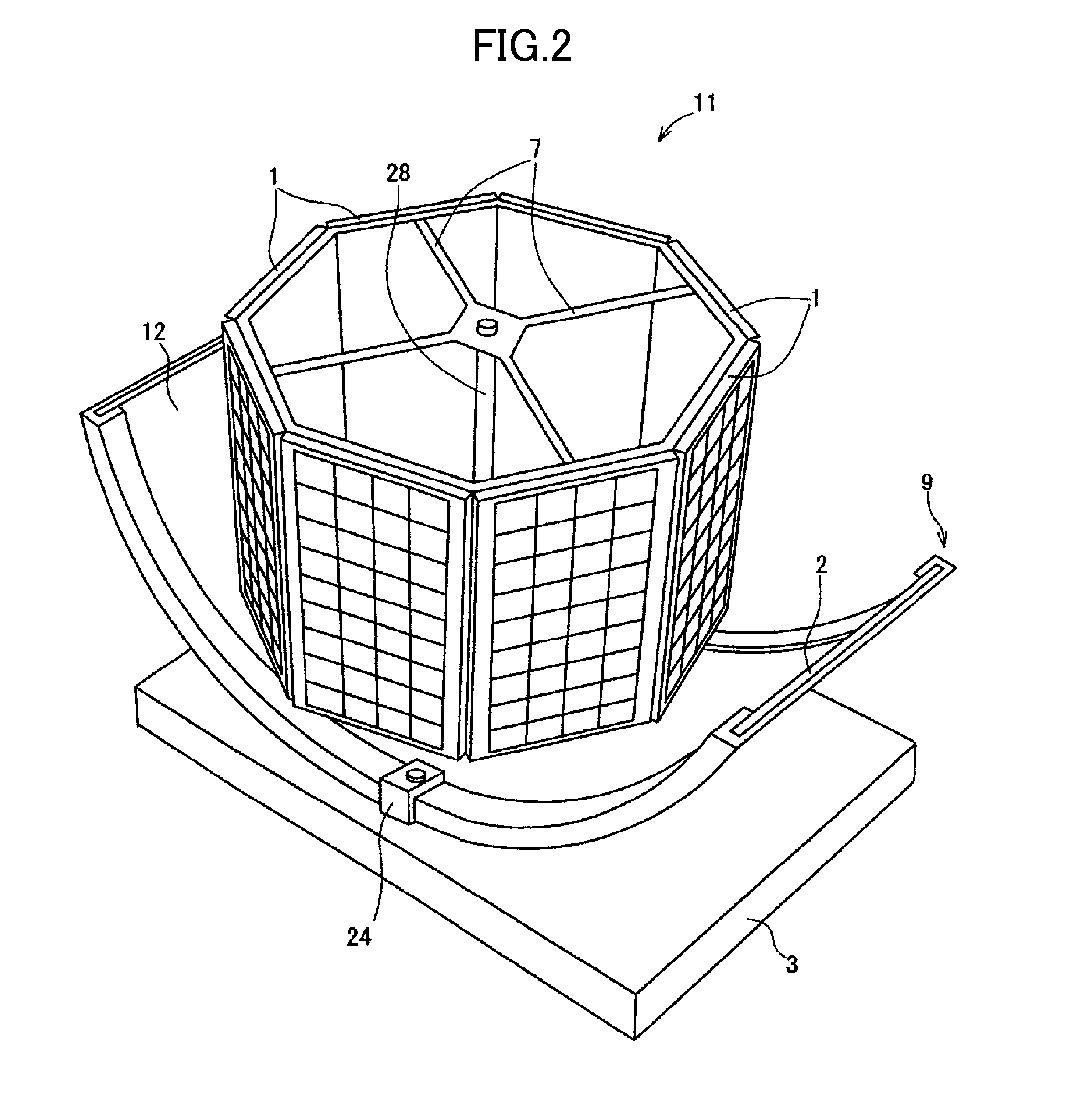
[0045]In the solar power generation apparatus the rotation shaft 28 is installed so as to extend in the vertical direction, and thereby it is possible to pile up plural solar cell panel bodies 11 in the vertical direction. Thereby, it is possible to increase a power generation amount.
[0046]The installation means of the curved mirror holder 9 shown in FIG. 1 may use, for example, means shown in FIG. 3. A solar power generation apparatus shown in FIG. 3 includes a solar cell panel body 11, a base 3, a cradle 37 vertically erected from the base 3, a strut 34, and a curved mirror holder 32.
[0047]The cradle 37 and the strut 34 have a plurality of through-holes (or long holes) in the longitudinal direction, and the curved mirror holder 32 has a plurality of bolt holes 36 on its side surface. The curved mirror holder 32 is installed at the cradle 37 and the strut 34 using bolts. As an installation method thereof, a bolt 39 is screwed into the selected bolt hole 36 of the curved mirror hol...
fourth embodiment
[0049]FIG. 4 shows a solar power generation apparatus which includes a solar cell panel body 11, a curved mirror 2, a rotation shaft 8, a strut 44, a swivel base 41, a sun position detecting means (not shown), an arm revolution driving means (not shown), a swivel base driving means (not shown), and a base 3.
[0050]The arm revolution driving means and the swivel base driving means are motors, and a motor such as a stepping motor which can control a rotation angle is preferable. Each driving means is electrically connected to the sun position detecting means so as to communicate with each other, and is operated in response to signals output from the sun position detecting means. The operation may be performed using some of power obtained through solar power generation.
[0051]The sun position detecting means includes a photodiode as a sensor, detects the position (azimuth and altitude) of the sun, and outputs a signal indicating the position. When the position of the sun cannot be detec...
PUM
 Abstract
Description
Claims
Application Information
 - R&D
- Intellectual Property
- Life Sciences
- Materials
- Tech Scout
- Unparalleled Data Quality
- Higher Quality Content
- 60% Fewer Hallucinations
Browse by: Latest US Patents, China's latest patents, Technical Efficacy Thesaurus, Application Domain, Technology Topic, Popular Technical Reports.
© 2025 PatSnap. All rights reserved.Legal|Privacy policy|Modern Slavery Act Transparency Statement|Sitemap|About US| Contact US: help@patsnap.com


