Active design of exhaust sounds
a technology of active design and exhaust gas, applied in the direction of electrophonic musical instruments, machines/engines, instruments, etc., can solve the problems of reducing the efficiency of the combustion engine, destructive interference, and the sound actually leaving the exhaust gas system is not appealing to a user
- Summary
- Abstract
- Description
- Claims
- Application Information
AI Technical Summary
Benefits of technology
Problems solved by technology
Method used
Image
Examples
first embodiment
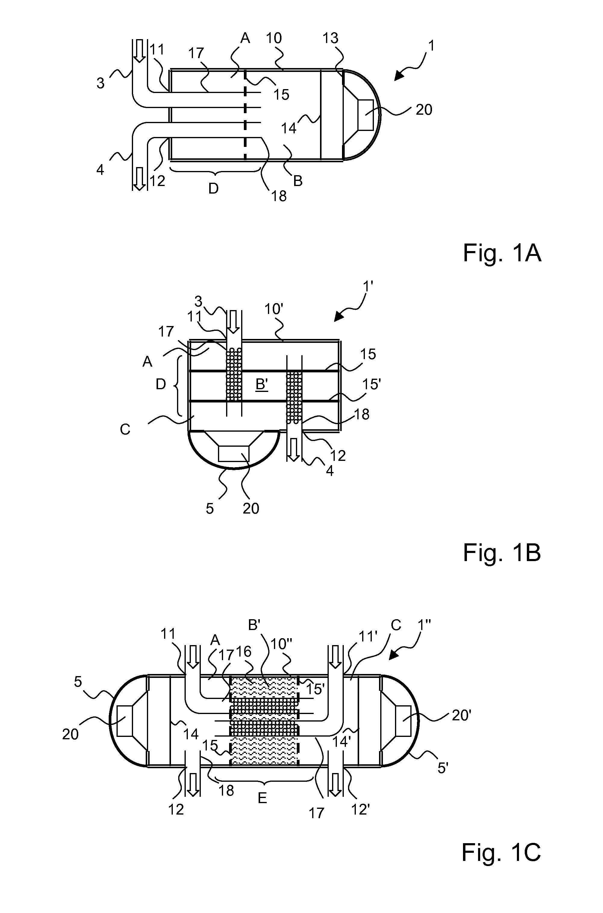
[0047]A schematic cross-sectional view of a sound generator for an active noise control system is shown in FIG. 1A.
[0048]The sound generator marked overall with reference number 1 comprises a generally cylinder-shaped casing 10 made of stainless steel. An exhaust gas inlet 11 connected to a supply duct 3 and an exhaust gas outlet 12 connected to an exhaust duct 4 are provided at a basal plane of the casing 10. The supply duct 3 may become fluidly connected to a combustion engine of a vehicle and the exhaust duct 4 may become fluidly connected to a tailpipe. A perforated bridge wall 15 made of stainless steel is coupled to the casing 10 so as to define two chambers A, B within the casing 10. The chambers A, B are separated from one another by the bridge wall 15. The supply duct 3 connected to the exhaust gas inlet 11 continues within the casing 10 as an unperforated supply conduit 17, and the exhaust duct 4 connected to the exhaust gas outlet 12 continues within the casing 10 as an ...
second embodiment
[0049]In the following, a sound generator 1′ is explained by reference to FIG. 1B. FIG. 1B shows a schematic cross-sectional view of the sound generator 1′.
[0050]The sound generator marked overall with reference number 1′ comprises a (first) generally cube-shaped casing 10′ made of zinc coated tinplate. An exhaust gas inlet 11 connected to a supply duct 3 and an exhaust gas outlet 12 connected to an exhaust duct 4 are provided at opposing sides of the casing 10′. Two parallel unperforated bridge walls 15, 15′ made of zinc coated tinplate are coupled spaced-apart from one another to the casing 10′ so as to define three chambers A, B′, C within the casing 10′. The supply duct 3 connected to the exhaust gas inlet 11 continues within the casing 10′ as a supply conduit 17, and the exhaust duct 4 connected to the exhaust gas outlet 12 continues within the casing 10′ as a exhaust conduit 18. Within the casing 10′, the supply conduit 17 and the exhaust conduit 18 are arranged in parallel in...
third embodiment
[0051]In the following, a sound generator 1″ is explained by reference to FIG. 1C. FIG. 1C shows a schematic cross-sectional view of the sound generator 1″.
[0052]The sound generator marked overall with reference number 1″ comprises a generally cylinder-shaped casing 10″ made of stainless steel. Two exhaust gas inlets 11, 11′ each connected to an supply duct and two exhaust gas outlets 12, 12′ each connected to an exhaust duct are provided at opposing sides of the casing 10″. Two parallel perforated bridge walls 15, 15′ made of stainless steel are coupled spaced-apart from one another to the casing 10″ so as to define three chambers A, B′, C within the casing 10″. The supply ducts connected to the exhaust gas inlets 11, 11′ each continue within the casing 10″ as a supply conduits 17, 17′ and the exhaust ducts connected to the exhaust gas outlets 12, 12′ each continue within the casing 10″ as a exhaust conduits 18, 18′. The supply conduits 17, 17′ are bent such that within the casing ...
PUM
 Abstract
Description
Claims
Application Information
 - R&D
- Intellectual Property
- Life Sciences
- Materials
- Tech Scout
- Unparalleled Data Quality
- Higher Quality Content
- 60% Fewer Hallucinations
Browse by: Latest US Patents, China's latest patents, Technical Efficacy Thesaurus, Application Domain, Technology Topic, Popular Technical Reports.
© 2025 PatSnap. All rights reserved.Legal|Privacy policy|Modern Slavery Act Transparency Statement|Sitemap|About US| Contact US: help@patsnap.com


