Device and method for obtaining vital sign information of a living being

a technology of vital signs and devices, applied in the field of devices and corresponding methods for obtaining vital signs of living beings, can solve the problems of image-based vital signs, difficult and even impossible extraction of vital signs in some cases, and achieve the effect of improving accuracy and reliability

Inactive Publication Date: 2015-09-17
KONINKLJIJKE PHILIPS NV
View PDF2 Cites 21 Cited by
  • Summary
  • Abstract
  • Description
  • Claims
  • Application Information

AI Technical Summary

Benefits of technology

[0006]It is an object of the present invention to provide a device and a corresponding method for obtaining vital sign information of a living b

Problems solved by technology

One major problem encountered in image-based (e.g. camera-based) vital signs occurs when no dominant light is present in the environment.
The settings of the light sources could be varying over time which leads to dram

Method used


Image

  • Device and method for obtaining vital sign information of a living being
  • Device and method for obtaining vital sign information of a living being
  • Device and method for obtaining vital sign information of a living being

Examples


first embodiment

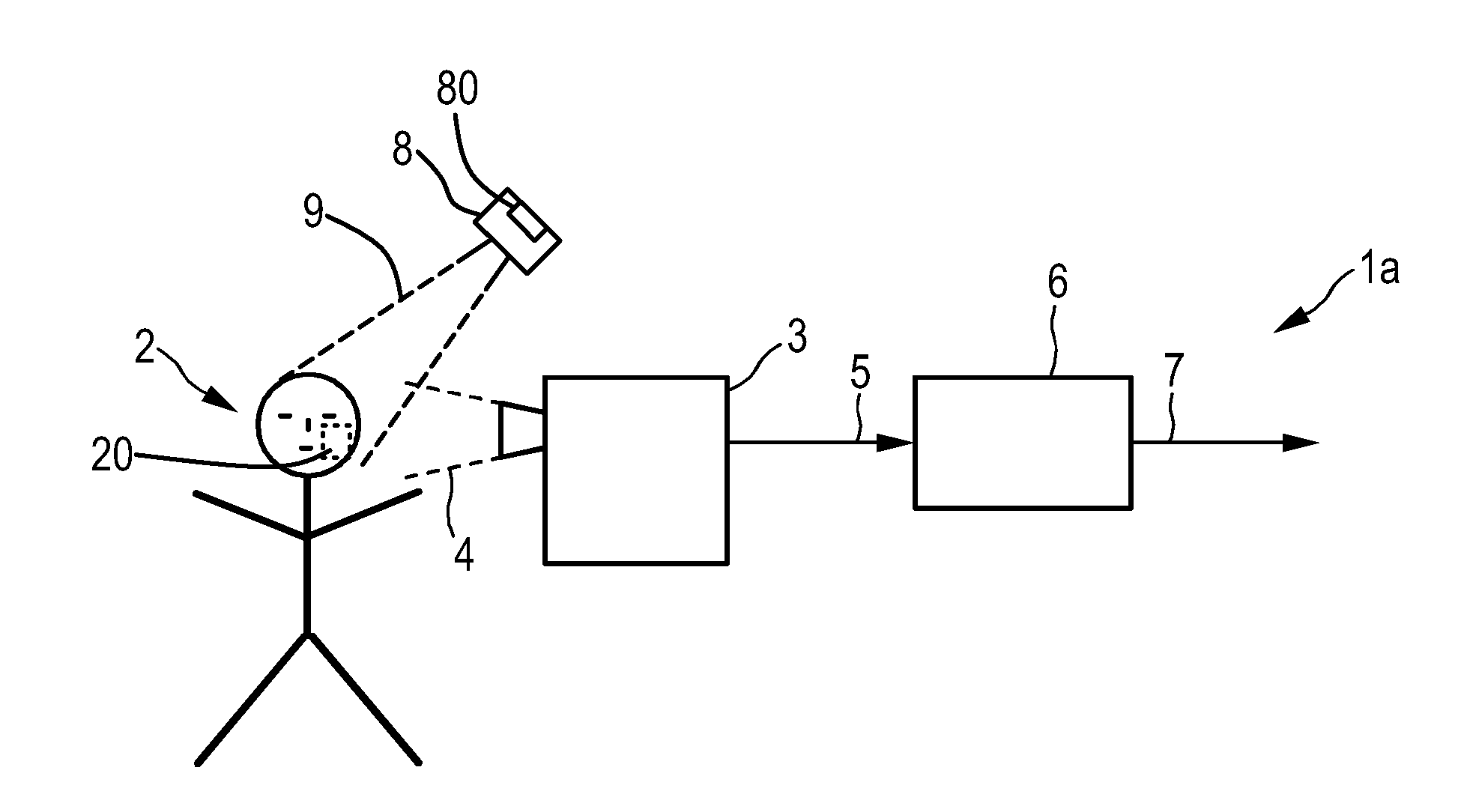
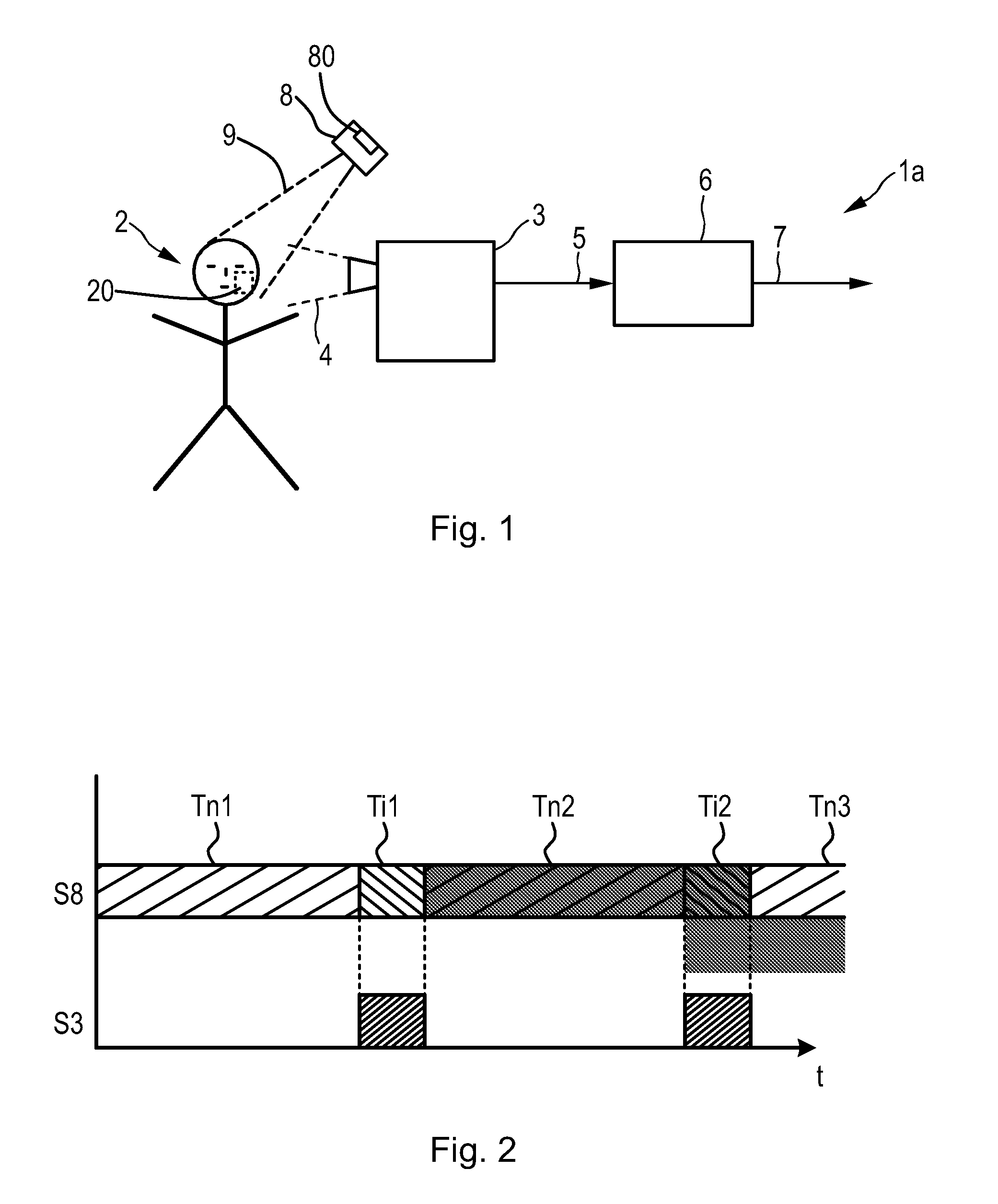
[0040]FIG. 1 shows a device 1a for obtaining vital sign information of a living being 2, e.g. a patient in a hospital, an elderly person monitored in the bed at home or a person doing sports in a fitness club, according to the present invention. The device 1a comprises a detection unit 3 for receiving light 4 in at least one wavelength interval reflected from at least a region of interest of the living being 2 and for generating an input signal 5 from the received light 4. The detection unit 3 is, for instance, configured to register spatio-temporal variations of received light 4, and is preferably an imaging unit for taking images, such as a video camera that substantially continuously or at regular intervals takes images of the living being 2 or at least a region of interest (ROI) 20 of the living being 2.

[0041]The device 1a further comprises a processing unit 6 for processing the input signal 5 and deriving vital sign information 7 of said living being 2 from said input signal 5 ...

second embodiment

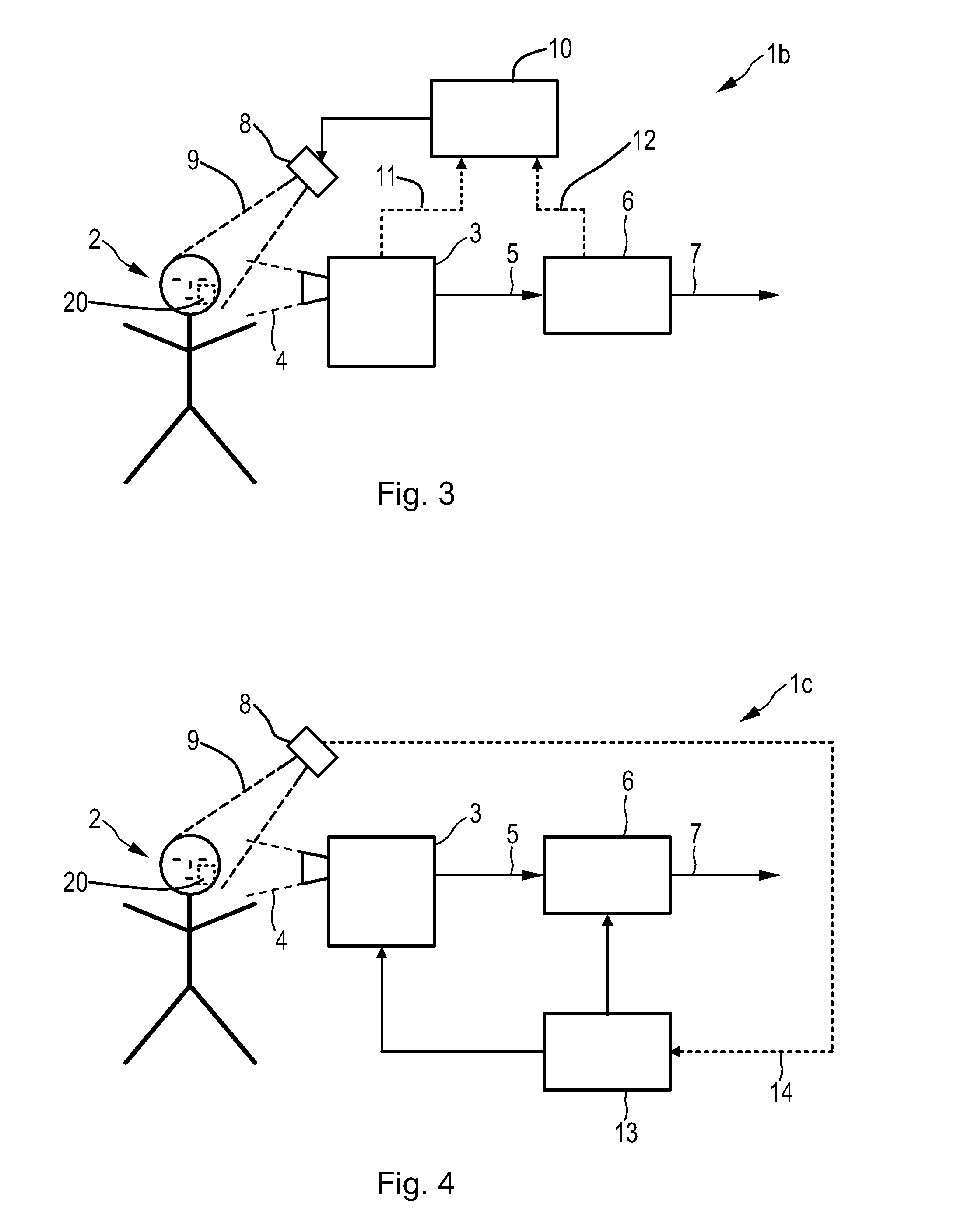
[0056]FIG. 3 shows a device 1b for obtaining vital sign information of a living being 2. In this embodiment employing an active mode a control unit 10 is provided for controlling the illumination unit 6 to illuminate at least said region of interest 20 during said illumination intervals with light optimized for vital sign measurements.

[0057]In an implementation the control unit 10 is controlled by a user or a remote operator or is preprogrammed.

[0058]Alternatively, the control unit 10 is coupled to the detection unit 3 and / or the processing unit, as indicated in FIG. 3 by broken lines 11 and 12, to synchronize the illumination of said at least one region of interest 20 by said illumination unit 8 with the reception of light and / or generation of input signals by said detection unit 3 and / or with said processing of input signal by said processing unit 6. This further provides the ability to adaptively control the illumination during the illumination intervals based on the obtained vit...

third embodiment

[0059]FIG. 4 shows a device 1c for obtaining vital sign information of a living being 2. In this embodiment a control unit 13 is provided for controlling said detection unit 3 to receive light and / or generate input signals only during said illumination intervals and / or for controlling said processing unit 6 to process only portions of input signals 5 generated from light received during said illumination intervals. Preferably, said control unit 13 is coupled to the illumination unit 8, as indicated by broken line 14 to control the detection unit 3 and / or the processing unit 6 based on the illumination intervals, which may thus be variable in time and duration. Alternatively, the control unit 13 may be preprogrammed according to a fixed timing of illumination intervals.


PUM


Abstract

The present invention relates to a device (1) and method for obtaining vital sign information of a living being (2). The proposed device (1) comprises a detection unit (3) for receiving light (4) in at least one wavelength interval reflected from at least a region of interest (20) of a living being (2) and for generating an input signal (5) from the received light (4), a processing unit (6) for processing the input signal (5) and deriving vital sign information (7) of said living being from said input signal (5) by use of remote photoplethysmography, and an illumination unit (8) for illuminating at least said region of interest (20) during illumination intervals with light, wherein said light during said illumination intervals is optimized for deriving vital sign information from an input signal generated by use of remote photoplethysmography from received light reflected from said region of interest.

Description

FIELD OF THE INVENTION[0001]The present invention relates to a device and a corresponding method for obtaining vital sign information of a living being.BACKGROUND OF THE INVENTION[0002]Unobtrusive vital sign monitoring using a video camera, or remote PPG (photoplethysmography), has been demonstrated and found relevant for patient monitoring. Remote photoplethysmographic imaging is, for instance, described in Wim Verkruysse, Lars O. Svaasand, and J. Stuart Nelson, “Remote plethysmographic imaging using ambient light”, Optics Express, Vol. 16, No. 26, December 2008. It is based on the principle that temporal variations in blood volume in the skin lead to variations in light absorptions by the skin. Such variations can be registered by a video camera that takes images of a skin area, e.g. the face, while processing calculates the pixel average over a manually selected region (typically part of the cheek in this system). By looking at periodic variations of this average signal, the hear...

Claims


Application Information

Patent Timeline
IPC IPC(8): A61B5/026A61B5/0295A61B5/00
CPCA61B5/0261A61B5/7278A61B5/0295A61B2560/0247A61B2576/00A61B2562/0233A61B5/748A61B5/02416A61B5/02433A61B5/14551A61B5/7203G06T7/254G06T2207/10016G06T2207/30076A61B5/024
Inventor BROERS, HARRYMANS, JOOST ADOLFJEANNE, VINCENT
Owner KONINKLJIJKE PHILIPS NV
Why Eureka
Try Eureka