
Method of manufacturing rotogravure cylinders

Active Publication Date: 2015-09-17
ICR IOANNOU SA
View PDF2 Cites 4 Cited by
  • Summary
  • Abstract
  • Description
  • Claims
  • Application Information

AI Technical Summary

Benefits of technology

The present invention provides a manufacturing method of a rotogravure cylinder with an aluminum base, a copper support, and a hard copper layer that has good reliability. This method simplifies the manufacturing process of the cylinder compared to the prior art method using soft copper surface plating. The coating layers are thin, with low porosity, which improves the properties of the resulting cylinder. The circumferential layer has a thickness of at least 50 μm, which corresponds to the thickness of the copper engraving layer. Overall, this invention provides an improved manufacturing method for rotogravure cylinders with better reliability and properties.

Problems solved by technology

However, aluminum is an electrochemically passive material and it is quite challenging to electro-copper plate it.
This has limited the use of aluminium for the base of the cylinder.
In further investigations on the cylinders manufactured in accordance with WO2011 / 073695A2 it was however observed that the reliability of the cylinders was less than desired.
Particularly, about 1-5% of the cylinders turned out defect relatively quickly after use by the customer.
However, the defects came irregularly, in an unpredictable manner.
Such defect clearly resulted in a need for replacement of the defect cylinders, which is undesired.

Method used


Image

  • Method of manufacturing rotogravure cylinders
  • Method of manufacturing rotogravure cylinders
  • Method of manufacturing rotogravure cylinders

Examples


Embodiment Construction

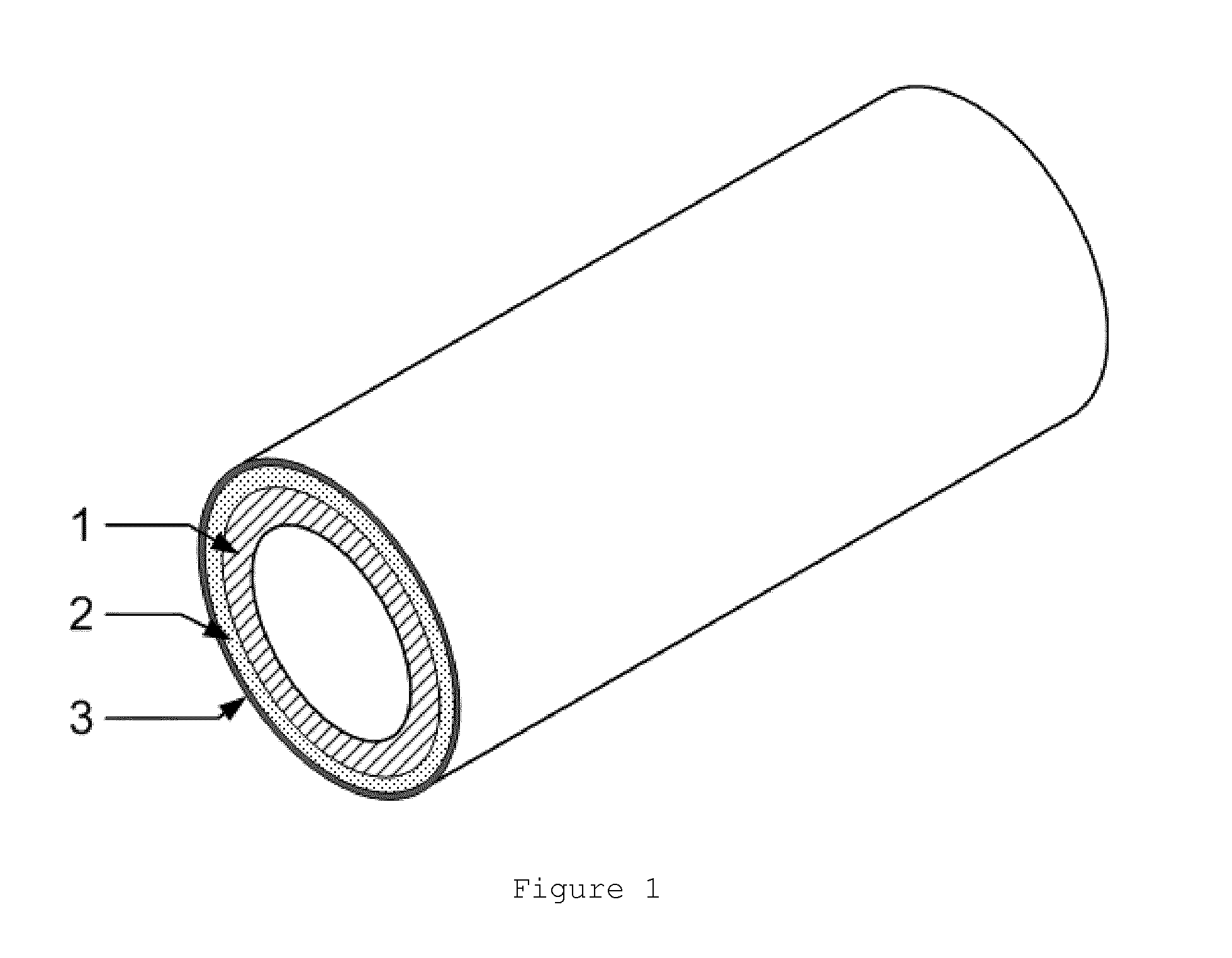
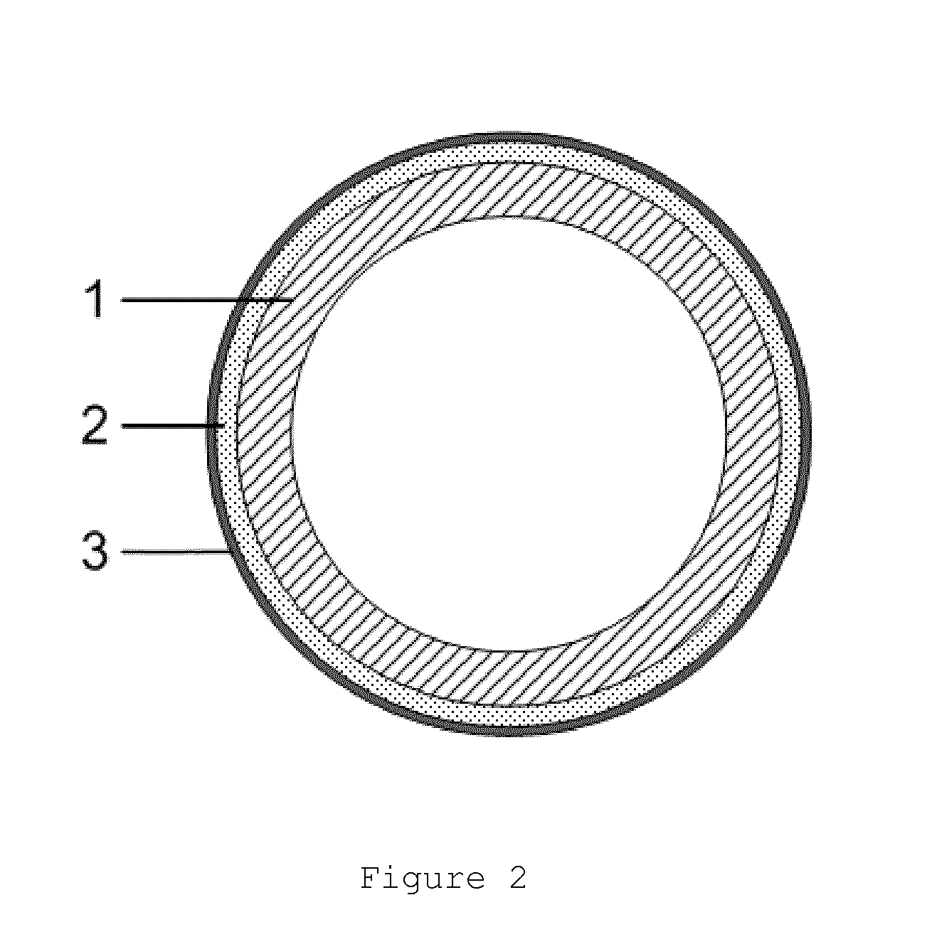
[0032]The FIGS. 1, 2 and 3 are not drawn to scale and they are only intended for illustrative purposes. Equal reference numerals in different figures refer to identical or corresponding figures.

[0033]The term ‘rotogravure cylinders” relates herein to rotogravure cylinders and / or any gravure cylinders used in the printing industry, particularly for the printing of packaging materials. The length of such cylinders is typically at least 1.0 meter, more preferably in the order of 1.5-2.5 meter.

[0034]The term ‘cylindrical base’ as used in the context of the present invention does not require the base to be a block-like material. Rather the base may be hollow. Alternatively, the base may comprise several layers, such as a steel core and an aluminium top layer.

[0035]The term aluminum in the present invention refers to pure aluminum, aluminum with small addition of other materials or aluminum alloys. Likewise, the term copper refers to pure copper, copper with small addition of other materi...


PUM

PropertyMeasurementUnit
Thicknessaaaaaaaaaa
Thicknessaaaaaaaaaa
Velocityaaaaaaaaaa

Abstract

The present invention describes a method for manufacturing rotogravure cylinders with a cylinder base made of aluminum. The method involves the coating of the cylinder surface with high velocity spraying, the copper plating in an appropriate solution, the engraving of the cylinder, and the hardening of the cylinder by chromium plating. The spraying process is accomplished by High-Velocity Air-Fuel or High-Velocity Oxygen-Fuel thermal spraying which leads to less surface porosity, better adhesion of the copper substrate and better dimensional accuracy. The advantage of this method is the elimination of the surface roughening process and the elimination of the preplating process. In addition, the end plates are manufactured partly from aluminum and partly from steel which further reduces the total weight of the cylinder. The elimination of these processes reduces the weight of the cylinder and the overall manufacturing time considerably.

Description

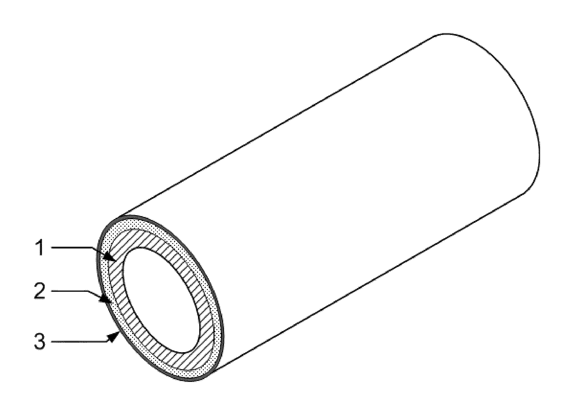
FIELD OF THE INVENTION[0001]The present invention refers to a method for manufacturing rotogravure or gravure cylinders.[0002]The invention also relates to the thus obtained rotogravure cylinders[0003]The invention further relates to the use of the rotogravure cylinders in the printing industry for the printing of packaging materials (by transfer of ink from the printing cylinder to the packaging material), such as for instance Intaglio printing processes.BACKGROUND OF THE INVENTION[0004]Gravure cylinders consist of the base of the cylinder (see FIG. 1 which shows such a cylinder), which is usually made of steel or aluminum (1, FIGS. 1 and 1, FIG. 2), a copper layer (2, FIGS. 1 and 2, FIG. 2) usually 0.5 to 1 mm thick and a protection layer, which is usually a chromium layer typically of 6 to 8 μm thick (3, FIGS. 1 and 3, FIG. 2).[0005]The copper layer is electroplated on the base of the cylinder and forms the surface which is engraved or etched either by chemical or electromechanic...

Claims


Application Information

Patent Timeline
IPC IPC(8): C25D5/10C25D7/04B41F13/187C25D5/48B32B15/01B32B1/00B65B61/26C25D5/44
CPCC25D5/10B65B61/26C25D7/04B41F13/187C25D5/48B32B15/017B32B1/00C25D5/44B41C1/18B41N1/20C25D3/38C25D5/36C25D11/38Y10T428/1275C23C4/18
Inventor IOANNOU, IOANNIS
Owner ICR IOANNOU SA
Learn More