MEMS motion sensor and method of manufacturing

Pending Publication Date: 2015-09-17
MOTION ENGINE
View PDF11 Cites 19 Cited by
  • Summary
  • Abstract
  • Description
  • Claims
  • Application Information

AI Technical Summary

Benefits of technology

[0018]In some embodiments, the resonant structure is shaped, sized and configured such that each of the resonant frequencies fx, fy and fz is substantially higher than sensing frequen

Problems solved by technology

However, due to the build-up of stresses in films deposited during the fabrication of these devices, processes for physical and chemical deposition are limited to only a few micrometers of material.
Consequently polysilicon devices tend to have small masses.
Small sensing masses provide low measurement sensitivity and higher vulnerability to thermal noise.
Additionally, since springs and com

Method used


Image

  • MEMS motion sensor and method of manufacturing
  • MEMS motion sensor and method of manufacturing
  • MEMS motion sensor and method of manufacturing

Examples


Embodiment Construction

[0065]In the following description, similar features of the drawings have been given similar reference numerals. To preserve the clarity of the drawings, some reference numerals have been omitted when they were already identified in a preceding figure.

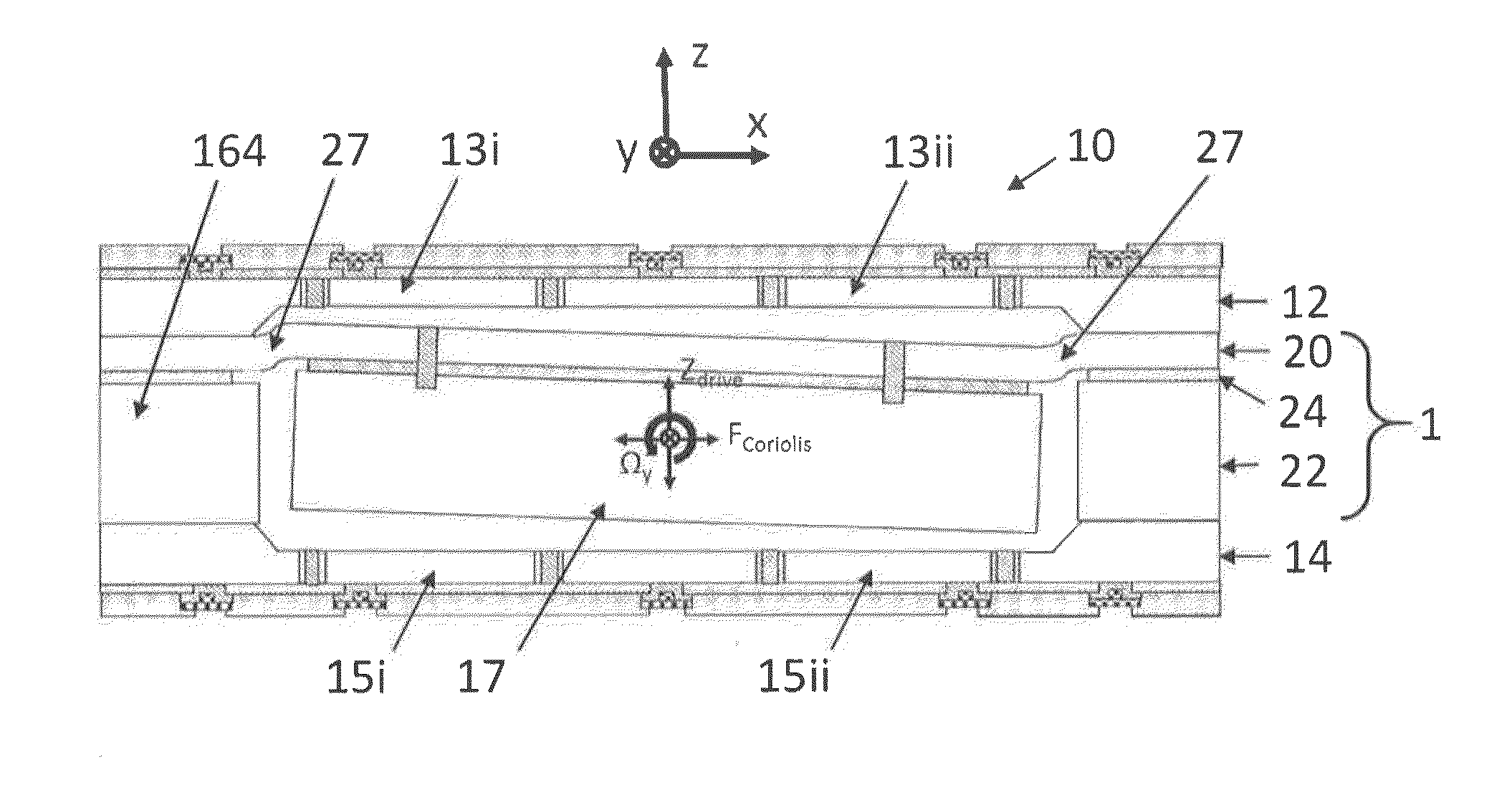
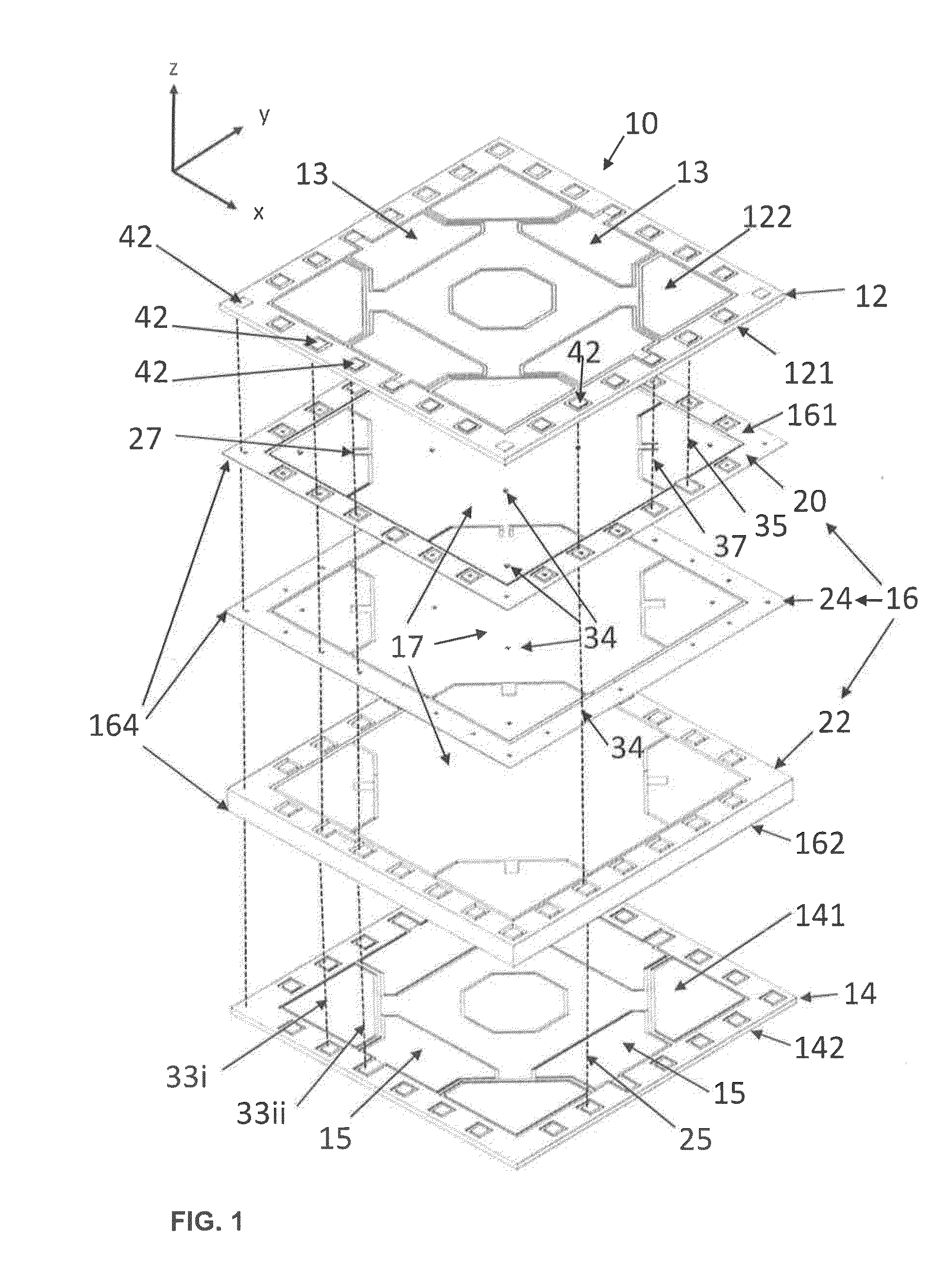
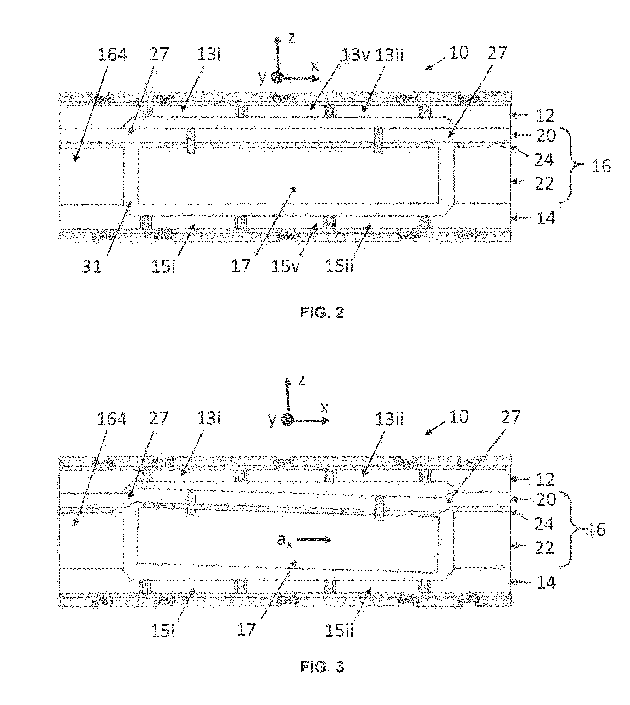
[0066]The present invention provides a MEMS motion sensor formed by a top cap wafer, a central MEMS wafer and a bottom cap wafer, the wafers being made of an electrically conducting material, such as silicon. Both the top and bottom cap wafers are provided with electrodes on both sides of a pendulous proof mass. The MEMS motion sensor also includes insulated conducting pathways, at least some of which extend from electrodes in the bottom cap wafer, through the MEMS wafer and to the top cap wafer, allowing routing or transmitting electrical signals sensed by the electrodes of the bottom cap through the MEMS wafer, and more specifically through the lateral frame of the sensor, from the bottom cap wafer to the top cap wafer. This architec...


PUM


Abstract

A MEMS motion sensor and its manufacturing method are provided. The sensor includes a MEMS wafer including a proof mass and flexible springs suspending the proof mass and enabling the proof mass to move relative to an outer frame along mutually orthogonal x, y and z axes. The sensor includes top and bottom cap wafers including top and bottom cap electrodes forming capacitors with the proof mass, the electrodes being configured to detect a motion of the proof mass. Electrical contacts are provided on the top cap wafer, some of which are connected to the respective top cap electrodes, while others are connected to the respective bottom cap electrodes by way of insulated conducting pathways, extending along the z axis from one of the respective bottom cap electrodes and upward successively through the bottom cap wafer, the outer frame of the MEMS wafer and the top cap wafer.

Description

RELATED APPLICATIONS[0001]This patent application is a continuation-in-part of international application no. PCT / CA2014 / 050730 filed on Aug. 1, 2014, which claims priority from U.S. application No. 61 / 861,786 filed on Aug. 2, 2013 and from U.S. application No. 61 / 861,821 filed on Aug. 2, 2013. The disclosures of each of these applications are incorporated herein by reference in their entirety.TECHNICAL FIELD OF THE INVENTION[0002]This invention relates to MicroElectroMechanical Systems (MEMS) motion sensors enabling electrical measurements from top and / or bottom caps. The invention also relates to a method for manufacturing MEMS motion sensors.BACKGROUND[0003]MEMS inertial sensors, which include accelerometers and angular rate sensors or gyroscopes, are used in a growing number of applications which have been increasing steadily over the past decade.[0004]Presently, most MEMS gyroscopes use polysilicon as their mechanical material. However, due to the build-up of stresses in films d...

Claims


Application Information

Patent Timeline
IPC IPC(8): G01C19/5712G01C25/00
CPCG01C25/00G01C19/5712G01C19/56G01C19/5769H01L2224/94G01C19/5755
Inventor BOYSEL, ROBERT MARKROSS, LOUIS
Owner MOTION ENGINE
Why Eureka
Try Eureka