Forward Flux Channel X-ray Source

a forward flux and x-ray source technology, applied in the field of radiation sources, can solve the problems of inherently limited heat dissipation of thin films, limited power output and efficiency of x-ray tubes with an angled reflective anode target, and often limited system speed and scope, so as to improve the conversion efficiency of electrons, reduce image acquisition times i x-ray imaging, and improve the effect of x-ray flux outpu

Active Publication Date: 2015-09-17
STELLARRAY
View PDF10 Cites 6 Cited by
  • Summary
  • Abstract
  • Description
  • Claims
  • Application Information

AI Technical Summary

Benefits of technology

[0015]It is an object of the invention to provide an x-ray source with superior conversion efficiency of electrons into x-rays and increased x-ray flux output, thereby decreasing image acquisition times i x-ray imaging systems and improving the speed and scope of x-ray analytical systems. It is a further object of the invention to provide a highly collimated source of x-ray flux. Another object of the invention is to enable improved x-ray imaging systems, including CT systems. A yet further object is to enable new imaging modalities such as parallel beam imaging, PCI and coded source imaging. An important advantage of the invention is the use of a larger x-ray generation area on the anode for a given x-ray spot size, which allows higher electrical power to be delivered to the anode than is possible with prior art sources. Another important advantage is the use of more of the electron beam to generate x-rays and reduce the inefficiency of prior art sources. A further advantage is the adaptability of the invention in source ranging from single channel sources to highly parallel array sources of x-rays. The ability to make large arrays of x-ray flux beams in linear, 2D and curved formats enables new imaging modalities not possible with prior art sources. The x-ray source of this system can be scaled to very large arrays of hundreds or thousands of x-ray flux beams.
[0016]This invention provides a source of x-ray flux in which x-rays are produced by e-beams impacting the inner walls of holes or channels formed in a metal anode such that most of the electrons reaching the channel impact an upper portion of said channel. A portion of the electrons from this primary impact will generate x-rays. Most of the electrons scatter but they continue to ricochet down the channel, most of them generating x-rays, until the beam is spent. A single channel source of high power efficiency and high power level x-rays may be made in this way, or the source can be of an array of such channels, to produce parallel collimated flux beams of x-rays.
[0017]The attached drawings are provided to help describe the structure, operation, and some embodiments of the source of the present invention. Numerous other designs, methods of operation and applications are within the meaning and scope of the invention.
[0018]FIG. 1 shows one embodiment of an FFC x-ray source in which the channel is slanted relative to the axis of the incoming electron beam so as the ensure the e-ebeam impacts the channel wall. The accompanying graphic shows the results of modeling run using the PENELOPE particle code to show where they have their primary impact on the channel, where they generate x-rays and where they scatter to generate more x-rays.
[0019]FIG. 2 shows another embodiment of an FFC x-ray source in which the channel has a conical shape with its narrow opening towards the cathode. The accompanying graphic shows the results of modeling run using the PENELOPE particle code to show where they have their primary impact on the channel, where they generate x-rays and where they scatter to generate more x-rays.
[0020]FIG. 3 shows another embodiment of an FFC x-ray source in which the channel has a first straight section and then a tapered section. The accompanying graphic shows the results of modeling run using the PENELOPE particle code to show where they have their primary impact on the channel, where they generate x-rays and where they scatter to generate more x-rays.

Problems solved by technology

In x-ray analytical systems, the speed and scope of the systems is often limited by the flux available from the x-ray source used.
Prior art x-ray tubes with an angled reflective anode target are limited in their power output and efficiency by the fact that when the e-beam hits the anode surface only a small part of it penetrates the target material to generate x-rays; nearly half of the e-beam is scattered off the target back towards the cathode and loses power to make x-rays.
Transmission anode x-ray sources have a fundamental limitation in generating x-ray flux in that the target must be a thin metal film to allow transmission of x-rays generated by the voltages used in imaging systems, but this thin film is inherently limited in the amount of heat it can dissipate and the heat it can handle before it melts or peals off the glass, beryllium or other flux exit window on which it is formed.
If collimators are used after the source, they will further diminish the already faint level of x-ray flux.
Angled xel array sources, such as those taught by U.S. Pat. No. 6,850,595 and U.S. Pat. No. 7,082,182, can handle higher power loads, but still may suffer anode pitting.
Prior art sources, however, are not adapted to deliver multiple parallel x-ray beamlets.
Prior art x-ray sources, however, are inadequate to make PCI useful for clinical and other large object imaging.
Current PCI imaging systems rely on single pencil beams of x-ray flux, which do not cover a clinically meaningful area, or synchrotron radiation sources, which are large, expensive and not available in clinical settings.
Electrons at the high kV energies used in x-ray generation, however, are traveling at relativistic speeds and do not change course easily.
This prior art source teaches the use of magnets near the anode to deflect the beam into the channel walls, but this would be very hard to do by the time the electrons approach the anode and would require impractically large magnets.
While an improvement over prior sources, this source, by having the anode on only one side of the channel does not make use of the scattered portion of the electron beam and will therefore still have limited efficiency and power.

Method used


Image

  • Forward Flux Channel X-ray Source
  • Forward Flux Channel X-ray Source
  • Forward Flux Channel X-ray Source

Examples


Embodiment Construction

[0034]Although the following detailed description delineates specific attributes of the invention and describes specific designs and fabrication procedures, those skilled in the arts of radiographic imaging or radiation source production will realize that many variations and alterations in the fabrication details and the basic structures are possible without departing from the generality of the processes and structures.

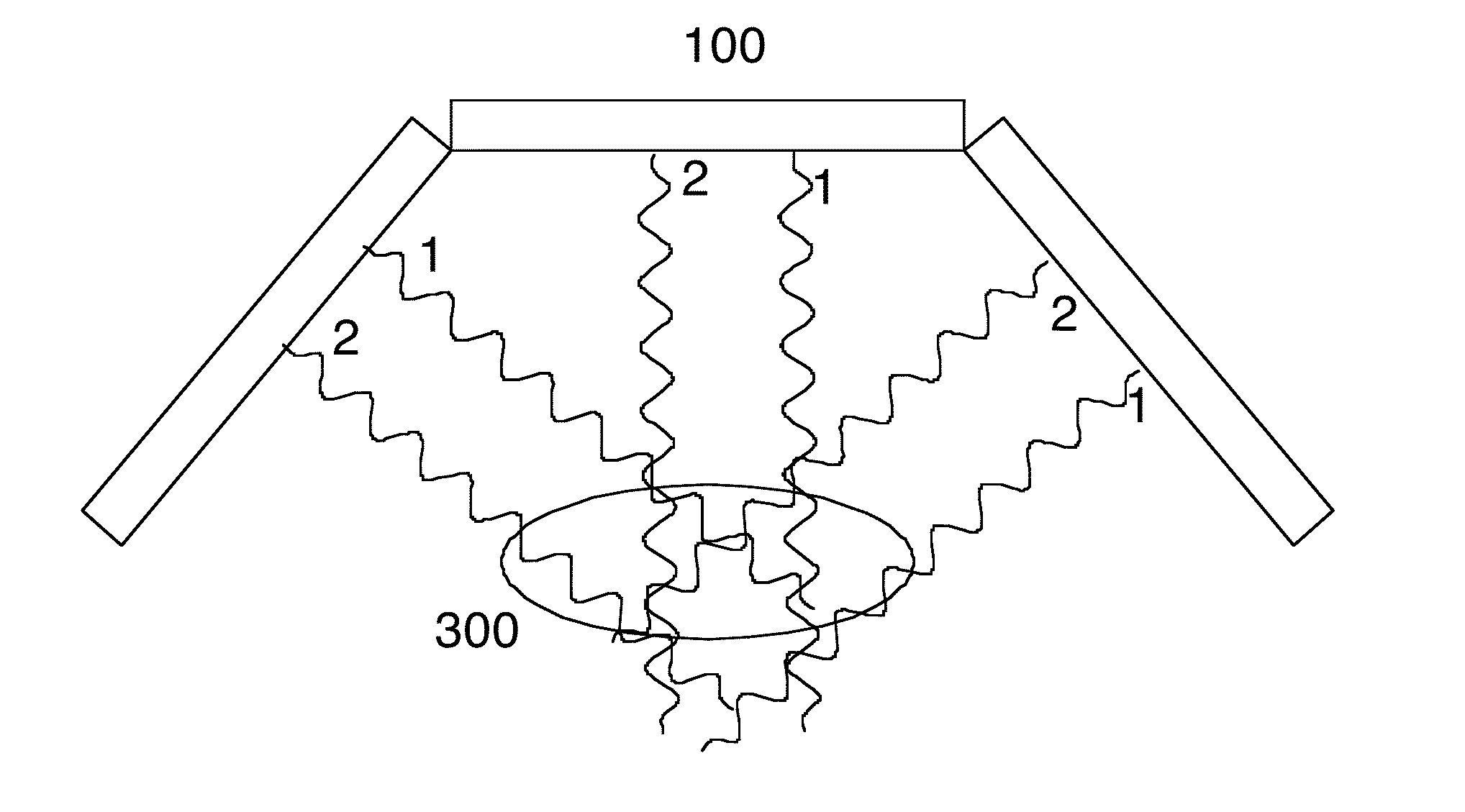
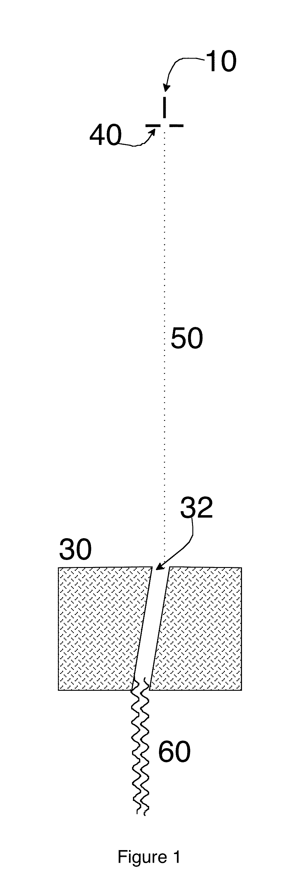
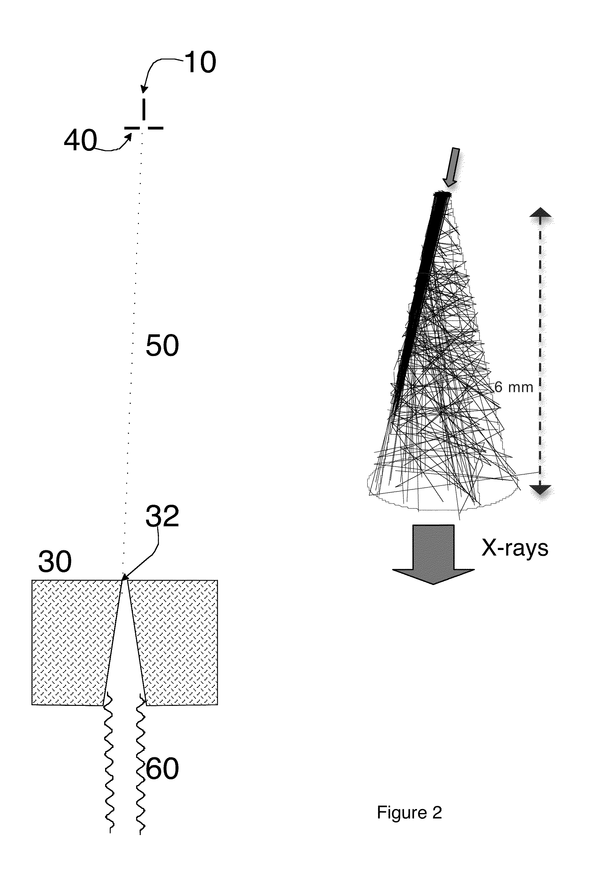
[0035]The FFC x-ray source comprises at least a cathode and a metal anode with at least one hole (termed a channel) through the anode such that x-rays may be produced by e-beams accelerated by an electrical potential between cathode and anode to impact the upper portion of the inner wall of the channel, which may also be called the upper acceptance region. The channel will typically be annular, but other channel shapes may also be used. A small portion of the electrons (estimated at under 25%) will produce x-rays from this primary impact but most of the electrons will...


PUM

PropertyMeasurementUnit
voltagesaaaaaaaaaa
diameteraaaaaaaaaa
angleaaaaaaaaaa

Abstract

This invention provides a source of x-ray flux in which x-rays are produced by e-beams impacting the inner walls of holes or channels formed in a metal anode such that most of the electrons reaching the channel impact an upper portion of said channel. A portion of the electrons from this primary impact will generate x-rays. Most of the electrons scatter but they continue to ricochet down the channel, most of them generating x-rays, until the beam is spent. A single channel source of high power efficiency and high power level x-rays may be made in this way, or the source can be of an array of such channels, to produce parallel collimated flux beams of x-rays.

Description

PRIORITY DATA[0001]Continuation in part of application Ser. No. 12 / 692,472, filed on Jan. 22, 2010, which is a continuation in part of application Ser. No. 12 / 201,741, filed on Aug. 29, 2008, issued as U.S. Pat. No. 8,155,273, which is a continuation in part of application Ser. No. 11 / 355,692, filed on Feb. 16, 2006, now abandoned, all of which are incorporated herein in their entirety.[0002]Provisional application No. 61 / 801,215, filed on Mar. 15, 2013.TECHNICAL FIELD OF THE INVENTION[0003]This invention relates in general to the field of radiation sources in which x-rays are produced by accelerated impact on metal anodes and more particularly to an x-ray source having superior conversion efficiency of electrons into x-rays and increased x-ray flux output, as well as to parallel beam x-ray sources formed of arrays of such individual x-ray sources.BACKGROUND OF THE INVENTION[0004]This invention provides a source of x-ray flux in which x-rays are produced by e-beams impacting the inn...

Claims


Application Information

Patent Timeline
Patent Type & Authority Applications(United States)
IPC IPC(8): H01J35/14H01J35/08H01J35/18G01N23/04
CPCH01J35/14G01N23/04H01J2235/08H01J35/18H01J2235/18H01J35/08G21K1/02H01J2235/086H01J35/116
Inventor EATON, MARK F.LUCENTE, MARK
Owner STELLARRAY
Why Eureka
Try Eureka