Method and Apparatus of an Architecture to Switch Equalization Based on Signal Delay Spread

a signal delay and equalization technology, applied in the direction of pulse manipulation, pulse technique, baseband system details, etc., can solve the problems of frequency offset, reduce the complexity of matrix inversion, reduce the power dissipation of the system, and prolong the battery life

Active Publication Date: 2015-09-24
TENSORCOM
View PDF5 Cites 10 Cited by
  • Summary
  • Abstract
  • Description
  • Claims
  • Application Information

AI Technical Summary

Benefits of technology

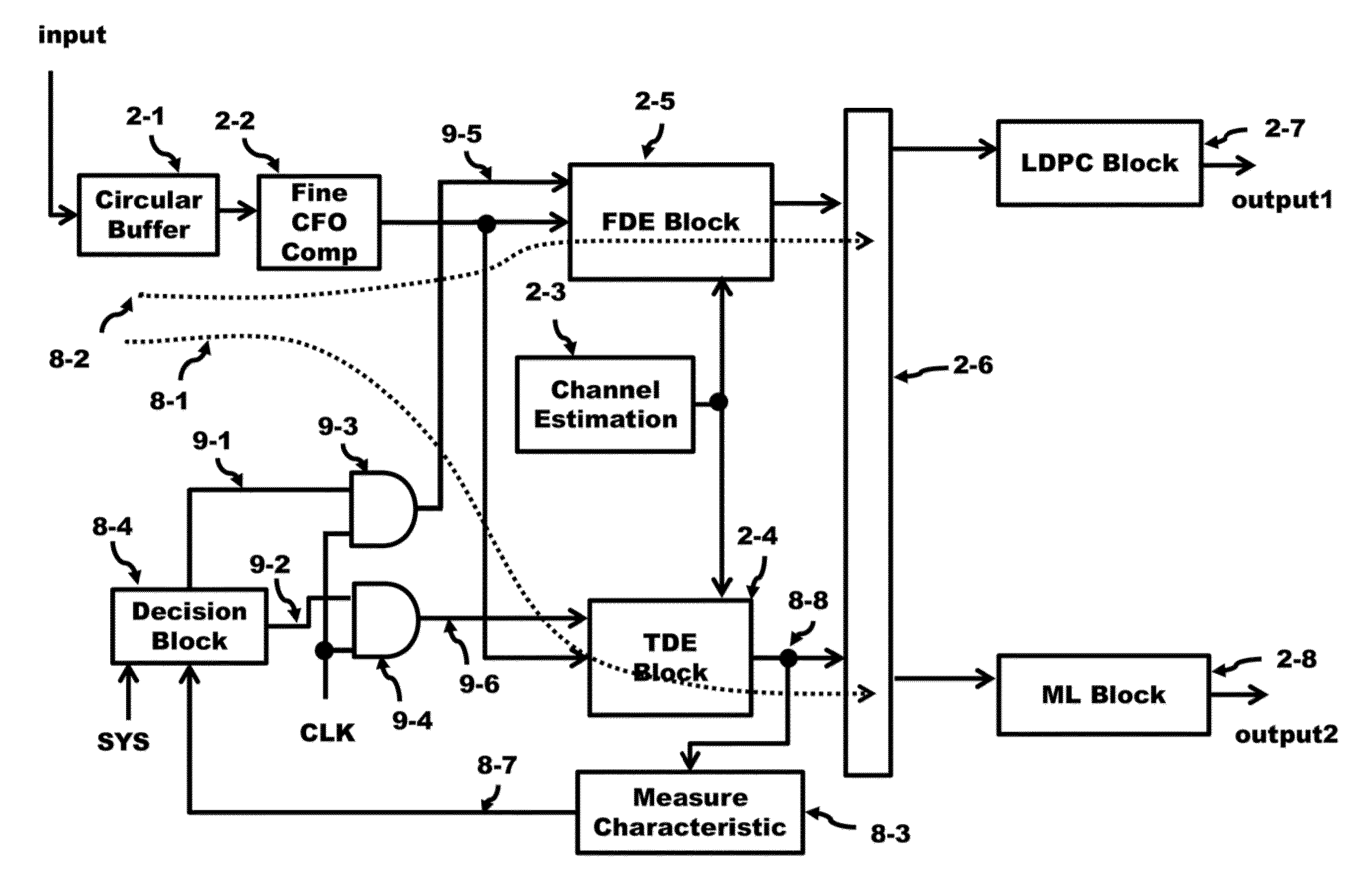
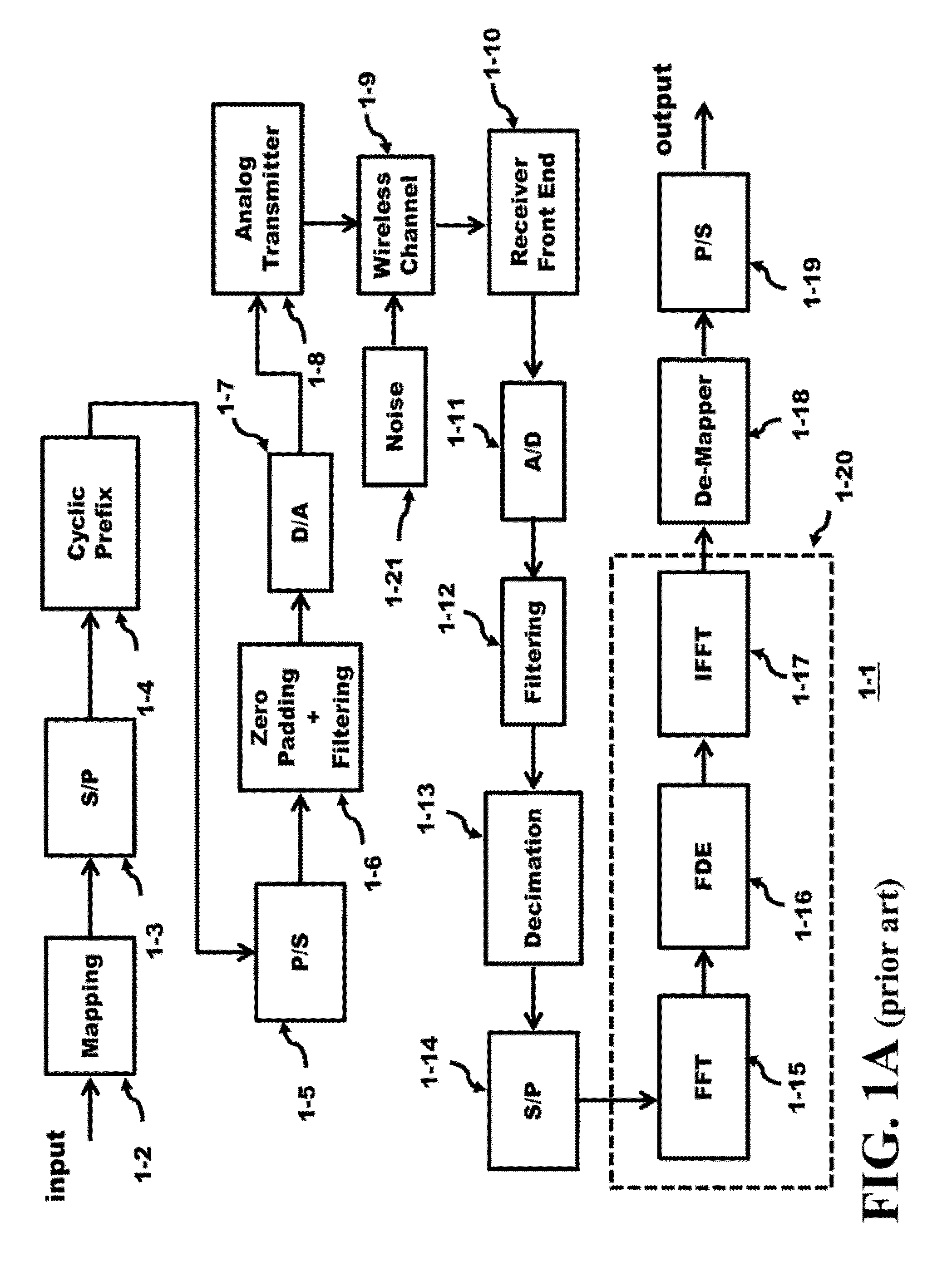
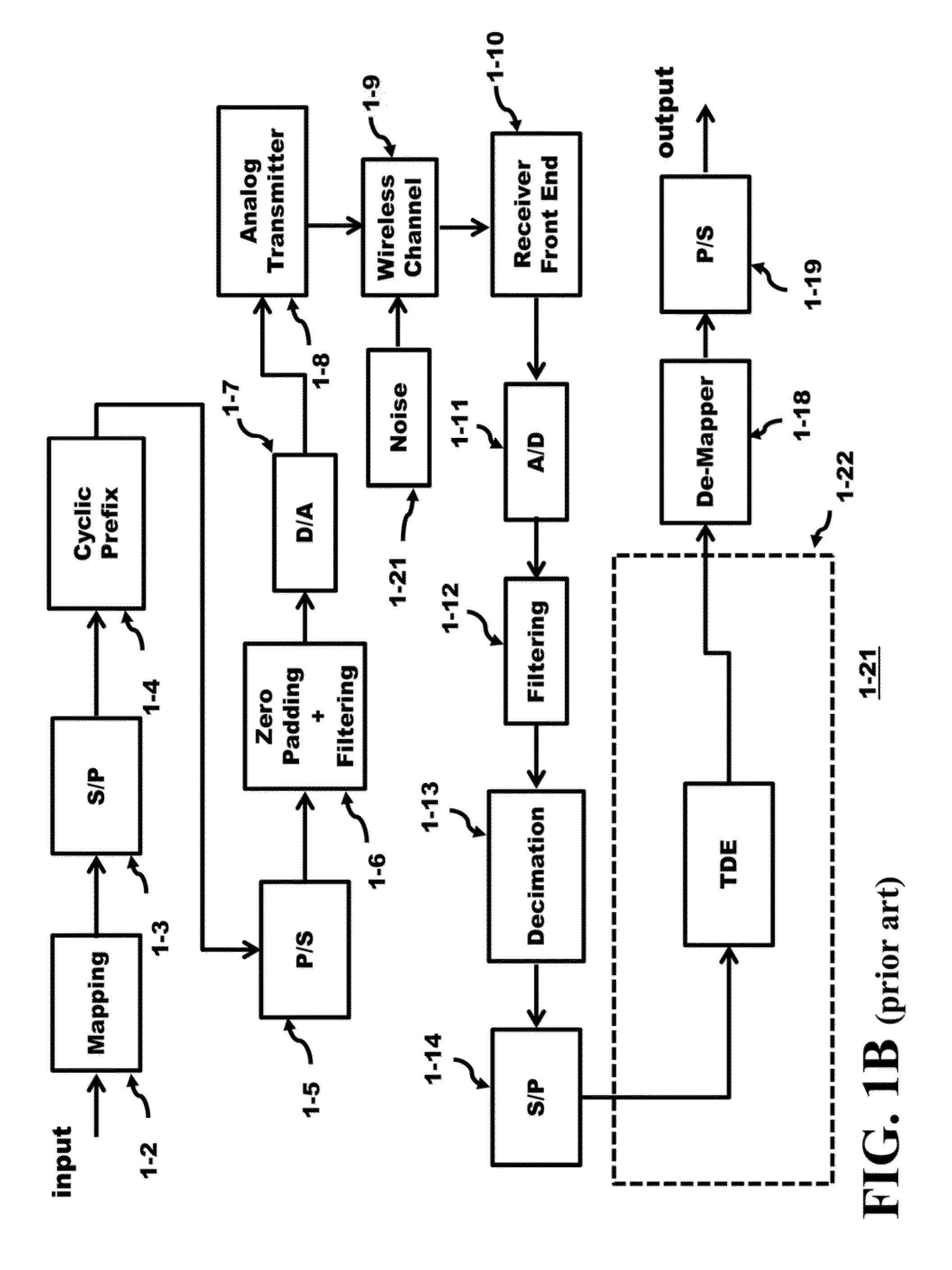
[0010]An inventive embodiment of one of the inventions is reducing the complexity of performing matrix inversion on a received signal when directional antennas are used in a 60 GHz system. The 60 GHz channel between the transmitter and receiver can have AWGN characteristics allowing a Time Domain Equalizer (TDE) to be used at the receiver instead of a Frequency Domain Equalizer (FDE). Incorporating the TDE in place of the FDE saves almost an order of magnitude in power dissipation. For portable units, such a savings is beneficial since the battery life can be extended.
[0011]Another inventive embodiment of one of the inventions is determining the signal quality of wireless channel using Error Vector Magnitude (EVM) and based on the characteristics of the received signal (delay spread, error rate, etc.) to switch the equalization operation from a system performing FDE to TDE and visa versa. Thus, based on the quality of the signal, the receiver adapts to the received signal to reduce the power dissipation of the system.
[0012]Another inventive embodiment of one of the inventions is combining the Equalizing switching along with the switching between the two modes of error detection: Low Density Parity Check (LDPC) and a Maximum Likelihood Block (ML). This provides versatility in the decoding of the signal.
[0013]One of th

Problems solved by technology

However, OFDM suffers from several deficiencies including peak to average power rati

Method used


Image

  • Method and Apparatus of an Architecture to Switch Equalization Based on Signal Delay Spread
  • Method and Apparatus of an Architecture to Switch Equalization Based on Signal Delay Spread
  • Method and Apparatus of an Architecture to Switch Equalization Based on Signal Delay Spread

Examples


Embodiment Construction

[0029]The WiGig standard transmits signals at 60 GHz allowing nearly a 10 GHz signal bandwidth capability. A desirable feature is to use directional (unidirectional) antennas at the transmitter to focus the energy to a receiver at a given location. Such a system offers flexibility in use. For example, if the distance between the transmitter and receiver to be either increased, the signal energy of unidirectional antenna allows for an improved Bit Error Rate Test (BERT) when compared to a omnidirectional antenna that is transmitting the same power levels. If the distance between the transmitter and receiver is decreased, then the signal quality improves when compared to an omnidirectional antenna that is transmitting the same power levels.

[0030]The directional antennas also offer an additional benefit for 60 GHz transport. Since the spreading of the signal energy is reduced from a directional antenna, reflected signals from structures off the signal path are reduced. A signal with a ...


PUM


Abstract

The 60 GHz channel between the transmitter and receiver can have AWGN characteristics allowing a Time Domain Equalizer (TDE) to be used at the receiver instead of a Frequency Domain Equalizer (FDE). The complexity of performing matrix inversion on a received signal is reduced when directional antennas are used in a 60 GHz system. Incorporating the TDE in place of the FDE saves almost an order of magnitude in power dissipation. For portable units, such a savings is beneficial since the battery life can be extended. The signal quality of wireless channel is based on the characteristics of the received signal to switch the equalization operation from a system performing FDE to TDE and vice versa. The receiver adapts to the received signal to reduce the power dissipation of the system.

Description

CROSS-REFERENCE TO OTHER APPLICATIONS[0001]The U.S. applications, Ser. No. 14 / 192,725 entitled “Method and Apparatus of a Fully-Pipelined FFT” filed on Feb. 27, 2014, and Ser. No. 14 / 165,505 entitled “Method and Apparatus of a Fully-Pipelined Layered LDPC Decoder” filed on Jan. 27, 2014, which are invented by at least one common inventor and assigned to the same assignee as the present application and incorporated herein by reference in its entirety.BACKGROUND OF THE INVENTION[0002]Federal Communications Commission (FCC) has allotted a spectrum of bandwidth in the 60 GHz frequency range (57 to 64 GHz). The Wireless Gigabit Alliance (WiGig) is targeting the standardization of this frequency band that will support data transmission rates up to 7 Gbps. Integrated circuits, formed in semiconductor die, offer high frequency operation in this millimeter wavelength range of frequencies. Some of these integrated circuits utilize Complementary Metal Oxide Semiconductor (CMOS), Silicon-German...

Claims


Application Information

Patent Timeline
IPC IPC(8): H04L25/03H04L27/26
CPCH04L25/03159H04L27/2601H04L25/03019H04L25/0212H04L2025/03414H04L27/2647
Inventor CHEUNG, RICKY LAP KEI
Owner TENSORCOM
Why Eureka
Try Eureka