Hybrid Interleaving Structure with Adaptive Phase Locked Loop for Variable Frequency Controlled Switching Converter

a phase lock loop and switching converter technology, applied in the direction of power conversion systems, pulse automatic control, dc-dc conversion, etc., can solve the problems of excessive power loss, slow transient response, and pulse distribution structure exhibit noise sensitivity

Active Publication Date: 2015-10-01
VIRGINIA TECH INTPROP INC
View PDF7 Cites 35 Cited by
  • Summary
  • Abstract
  • Description
  • Claims
  • Application Information

AI Technical Summary

Benefits of technology

[0013]In accordance with another aspect of the invention, a method of stabilizing a phase-locked loop (PLL) controlled multi-phase power converter, the method comprising steps of developing a small signal model of a transfer function between an on-time generator of the multi-phase power converter and a signal having pulses of constant amplitude and a frequency representing a phase differe...

Problems solved by technology

However, such a wide frequency range causes excessive power losses and problems with achieving correct interleaving angle for multi-phase operation.
However, transient response is slow because the phase manager (sometimes referred to as a phase splitter) arrangement, as will be discussed below, cannot immediately synchronize PFM pulses of all phases during step-up load transients.
Further, pulse distribution structures exhibit noise sensitivity due to ripple cancellation between the sum of the instantaneous currents delivered by the respective phases, particularly since the power delivery pulses do not overlap.
At operating points where ripple is substantially canceled, low-level noise can cause duty cycle jittering and results in higher output voltage ripple.
Adding an external ramp voltage having a slope Se can reduce jittering but the strong phase delay caused by using the ramp signal reduces ...

Method used


Image

  • Hybrid Interleaving Structure with Adaptive Phase Locked Loop for Variable Frequency Controlled Switching Converter
  • Hybrid Interleaving Structure with Adaptive Phase Locked Loop for Variable Frequency Controlled Switching Converter
  • Hybrid Interleaving Structure with Adaptive Phase Locked Loop for Variable Frequency Controlled Switching Converter

Examples


Embodiment Construction

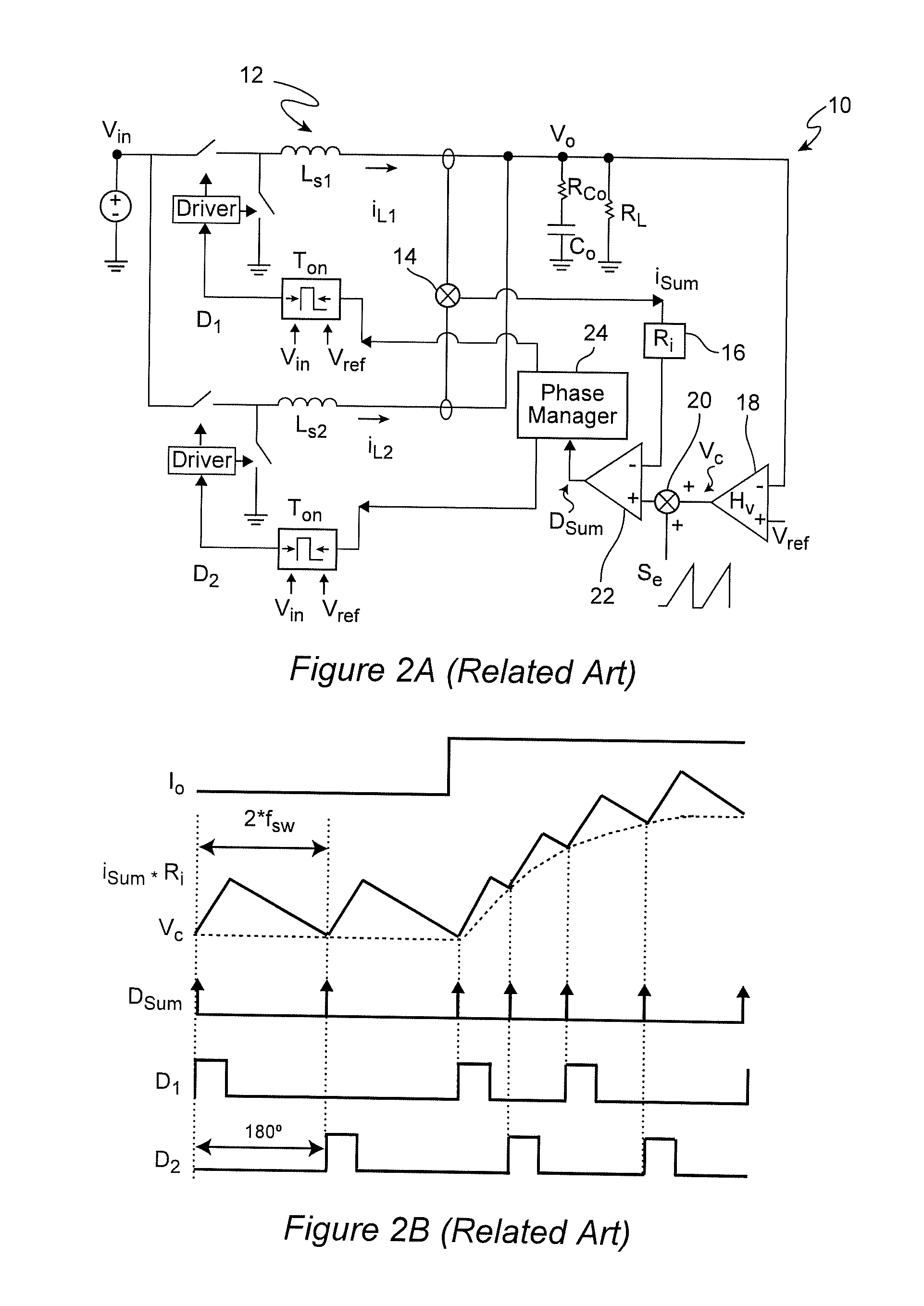
[0055]Referring now to the drawings, and more particularly to FIG. 2A, there is shown a simplified schematic diagram of a two-phase pulse distribution structure, alluded to above. Since this diagram is both simplified and generalized as well as being arranged to facilitate an understanding of a problem addressed by the invention, no portion of FIG. 2A is admitted to be prior art in regard to the present invention. In particular, the element labeled “Phase Manager”24 is essentially a commutator for distributing sequential pulses to different outputs as will be described in connection with FIG. 2B and result in the problems discussed below in connection with FIGS. 3 and 4 and is thus often implemented in logic for which many logic circuit designs will be apparent to those skilled in the art while other phase managers having a more complex function as will be described below are considered to be part of the invention. Phase manager 24 is, therefore, depicted as a fully generalized sing...


PUM


Abstract

In a multi-phase power converter using a phase-locked loop (PLL) arrangement for interleaving of pulse frequency modulated (PFM) pulses of the respective phases, improved transient response, improved stability of high bandwidth output voltage feedback loop, guaranteed stability of the PLL loop and avoidance of jittering and phase cancellation issues are achieved by anchoring the bandwidth at the frequency of peak phase margin. This methodology is applicable to multi-phase power conveners of any number of phases and any known or foreseeable topology for individual phases and is not only applicable to power converters operating under constant on-time control, but is extendable to ramp pulse modulation (RPM) control and hysteresis control. Interleaving of pulses from all phases is simplified through use of phase managers with a reduced number of PLLS using hybrid interleaving arrangements that do not exhibit jittering even when ripple is completely canceled.

Description

CROSS-REFERENCE TO RELATED APPLICATIONS[0001]This application claims benefit of priority of U.S. Provisional Application 61 / 973,590, filed Apr. 1, 2014, which is hereby incorporated by reference in its entirety.FIELD OF THE INVENTION[0002]The present invention generally relates to variable frequency controlled switching power converters and, more particularly, to assuring stability and adequate phase margins of both low bandwidth phase locked loops (PLLs) and high bandwidth output voltage feedback loops, particularly in multi-phase variable frequency controlled power converters.BACKGROUND OF THE INVENTION[0003]Variable frequency control has been widely used in DC-DC power converters since variable frequency control provides not only improved light load efficiency but also fast transient response and high bandwidth design to reduce capacitance requirements for filter capacitors; saving cost and size. The light load efficiency is increased by reducing switching frequency, fsw, when th...

Claims


Application Information

Patent Timeline
IPC IPC(8): G05F1/56
CPCG05F1/56H02M3/1584H03L7/06H02M3/1586
Inventor LIU, PEI-HSINLI, QIANGLEE, FRED C.
Owner VIRGINIA TECH INTPROP INC
Why Eureka
Try Eureka