Microwave plasma applicator with improved power uniformity

a microwave energy and applicator technology, applied in the field of microwave plasma systems, can solve the problems of large quantity of microwave energy used for creating a large quantity, inconvenient operation, and large size of air blower or compressor, so as to reduce the spacing between selected adjacent loops and prevent leakage of microwave energy. , the effect of increasing the uniformity of power absorption

Inactive Publication Date: 2015-10-01
MKS INSTR INC
View PDF7 Cites 11 Cited by
  • Summary
  • Abstract
  • Description
  • Claims
  • Application Information

AI Technical Summary

Benefits of technology

[0024]According to another aspect, a plasma discharge tube assembly for a plasma generating device is provided. The assembly includes a plasma discharge tube being substantially transparent to microwave energy and having a longitudinal axis. A conductive coil comprising an electrically conductive material is substantially helically wound around an outer surface of the plasma discharge tube. An electric field of the microwave energy induces an electric current in the conductive coil, the electric current affecting power absorption in the plasma discharge tube. A plurality of microwave chokes is disposed at each of two ends of the conductive coil, the microwave chokes substantially preventing leakage of the microwave energy from the plasma discharge tube.
[0025]In some exemplary embodiments, the conductive coil comprises a plurality of loops around the plasma discharge tube, the plurality of loops defining a pattern of spacing between adjacent loops, the pattern of spacing being sele...

Problems solved by technology

One technical difficulty in using microwave energy for creating a large quantity of reactive gaseous species in a plasma source is cooling the plasma discharge tube or dielectric window.
Air cooling can be used for the plasma discharge tube, but it is relatively inefficient compared with liquid cooling.
In addition, air cooling requires relatively large and expensive air blowers or compressors to remove a sufficient amount of heat.
Also, air cooling may not be compatible with modern clean room environments used for manufacturing ...

Method used


Image

  • Microwave plasma applicator with improved power uniformity
  • Microwave plasma applicator with improved power uniformity
  • Microwave plasma applicator with improved power uniformity

Examples


Embodiment Construction

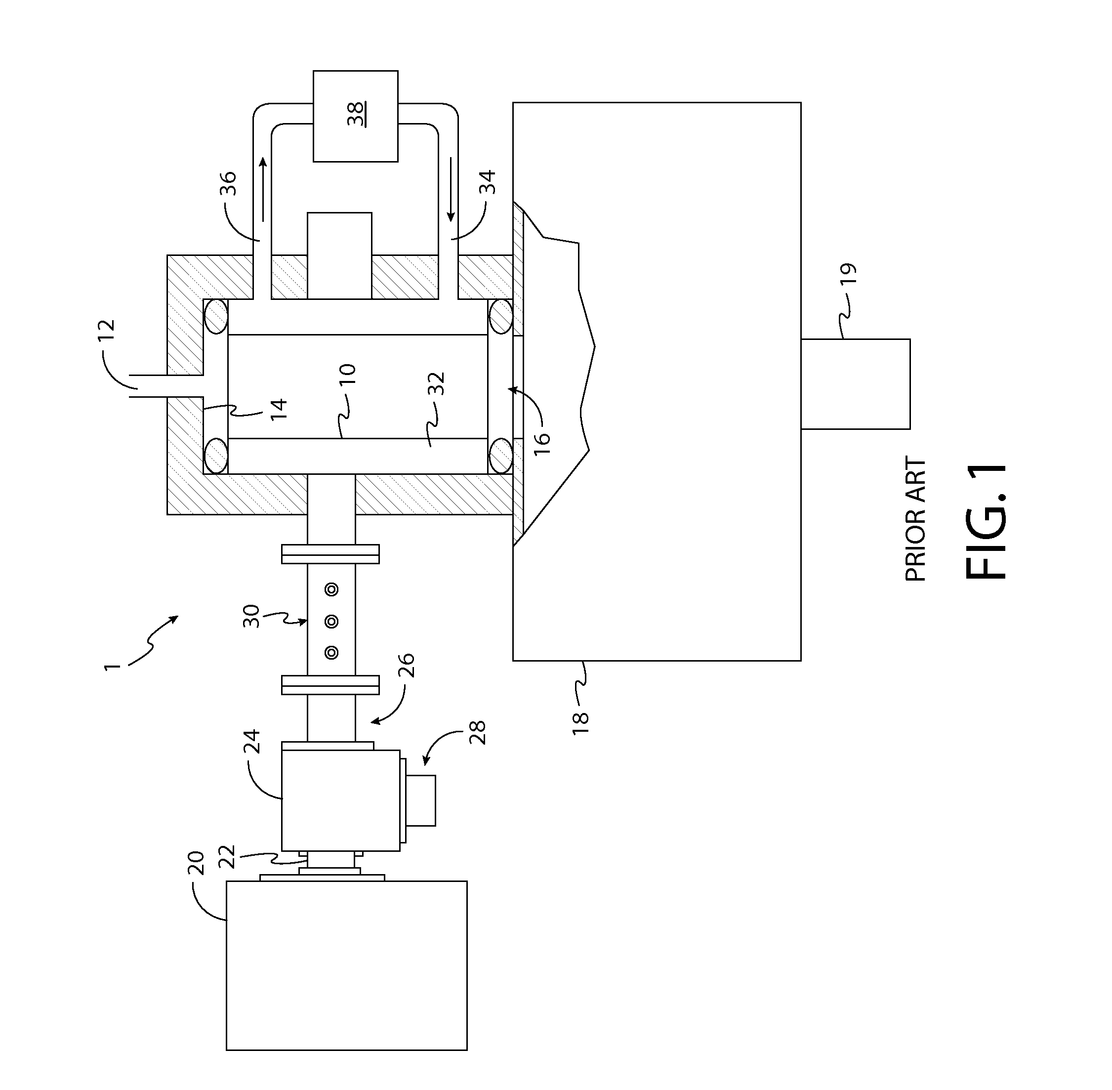
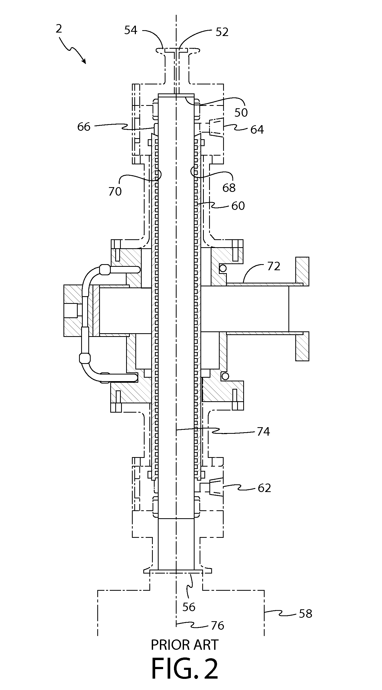
[0040]U.S. Pat. No. 5,625,259 (hereinafter, “the '259 patent”), incorporated herein in its entirety by reference, discloses that a microwave electric field oriented in a particular direction can be efficiently coupled to a microwave plasma discharge tube having a channel containing a microwave absorbing cooling liquid surrounding the plasma discharge tube in a certain path. For example, a microwave electric field oriented parallel to a longitudinal axis extending through the center of the plasma discharge tube will efficiently couple to the plasma discharge tube having a cooling channel encircling the tube in a helical path.

[0041]Furthermore, a microwave electric field oriented in a particular direction can be efficiently coupled to a dielectric window having one or more channels in contact with the window and containing a microwave absorbing cooling liquid. For example, a microwave electric field oriented parallel to the surface of the window will efficiently couple to a plasma dis...


PUM


Abstract

An apparatus for generating plasma includes a plasma discharge tube and a conductive coil helically wound around an outer surface of the plasma discharge tube. A waveguide is coupled to a microwave cavity surrounding the plasma discharge tube to guide the microwave energy into the plasma discharge tube such that the plasma is generated in the plasma discharge tube. The waveguide is positioned such that an electric field of the microwave energy is oriented at a predetermined angle with respect to the longitudinal axis of the plasma discharge tube. A resulting induced electric current in the conductive coil affects power absorption in the plasma discharge tube, the predetermined angle being selectable such that power absorption in the plasma discharge tube is according to a predetermined profile with respect to the longitudinal axis of the plasma discharge tube.

Description

BACKGROUND[0001]1. Technical Field[0002]This disclosure is related to microwave plasma systems and, more particularly, to a fluid-cooled microwave plasma applicator for producing reactive gaseous species for processing applications.[0003]2. Discussion of Related Art[0004]Reactive gases and gas mixtures are used in many industrial operations including the processing of materials such as semiconductor wafers for fabricating electronic and optical devices. Reactive gases can be used, for example, in thin film deposition and etching in microelectronics manufacturing to etch dielectric and semiconductor materials or various masking films such as photoresist and polyimide. Reactive gasses can be used to form dielectric films and metal films, and can also be used to clean wafer surfaces in various stages of wafer processing.[0005]Reactive species of gas molecules can be produced by exciting gas molecules in a plasma discharge. The discharge can be created with a plasma source by coupling e...

Claims


Application Information

Patent Timeline
IPC IPC(8): H01J37/32
CPCH01J37/32522H01J37/32229H01J37/32192H01J37/3222
Inventor CHEN, XINGJI, CHENGXIANGMADDEN, ERINPOKIDOV, ILYAWENZEL, KEVIN W.
Owner MKS INSTR INC
Why Eureka
Try Eureka