Wildlife exclusion composition and assembly

Active Publication Date: 2015-10-08
LAMPMAN WILDLIFE MANAGEMENT SERVICES
View PDF5 Cites 21 Cited by
  • Summary
  • Abstract
  • Description
  • Claims
  • Application Information

AI Technical Summary

Problems solved by technology

Prior systems may suffer from a number of shortcomings which include:I. inflexible installation limited to certain applications and certain target species;II. difficulty of construction;III. inability to withstand a wide range of climatic conditions including snow storms or heavy rains;IV. being prone to corrosion, material decomposition and other decay;V. the inability to discourage wildlife from attempting to cross conductive elements;VI. the inability to withstand blunt force impact such as snow plows;VII. being prone to vandalism and theft of exposed conductive elements; andVIII. inability to withstand high traffic count, tracked heavy equipment and machinery.< /
The commercialization of electrically conductive materials for the construction of roads or highways to control animal movement has been severely limited by the high cost and poor physical properties of such compositions.
This is because compared to conventional non conductive aggregate, metallic conductors are extremely expensive, while carbonaceous materials are both physically weak, and being semi-conductors must be used at very high concentrations in order to be effective.
However, the current technology suffers from numerous shortcomings, including for example the inability to control animals across a wide range of sizes.
For example, many of the existing assemblies are not suitable for controlling large agile animals which are capable of by-passing or jumping over such structures, while some animals with large hooves or paws can walk across cattle guards without being affected.
On the other hand, systems focused on larger animals do not have sufficient flexibility of design to address the problem of small animals, such as rodents, which might trespass territory inside buildings in order to reach foodstuff.
Electrically charged systems disclosed to date also suffer from shortcomings that the electrical circuits involve earth grounding and that the shock is delivered to the animal's hoof or paw as the electricity takes the path of least resistance.
The temporary nature and portability of such systems results in limited durability and makes them susceptible to theft and vandalism.
These systems can also be adversely impacted by flooding during spring thaw, or contaminated with detritus, all of which can result in the grid becoming dysfunctional due to various short circuits.
Many of the current technologies do not adequately address the fact that such assemblages must be robust enough to handle the high traffic counts, heavy axle weight, movement of heavy tracked equipment and machinery, and withstand the blunt force impact of snow plows in the winter.
Existing systems to manage the movement of wildlife do not address the need for heavy vehicles and equipment to cross these electrically charged barriers while the physical consequences of both heavy snow in the winter, and flooding and icing caused by melting snow near these installations reduces the effectiveness and increases the risk of vehicle accidents.
A commercial technology known as ‘Gap Zapper’™ utilizes a flexible mat consisting of two layers of rubber in which a proprietary compound applied to the top layer delivers a similar shock as an electrical fence to any animal that makes contact with it, but has insufficient strength to handle regular traffic of heavy vehicles, and has to be temporarily removed to allow tracked heavy equipment to cross.
Snow or heavy rain dramatically reduce the effectiveness of the Gap Zapper™.
Furthermore, various electrical animal control systems are relatively inflexible structures not easily adaptable to the wide range of types and sizes of wild and domestic animals Systems with exposed metallic conductors can be prone to damage to the exposed conductors.
Such systems have sporadic performance due to the impact of earth ground; the delivery of the shock across an animal's hoof or paw as the electrical current takes the path of least resistance and the impact of the snow and rain.

Method used


Image

  • Wildlife exclusion composition and assembly
  • Wildlife exclusion composition and assembly
  • Wildlife exclusion composition and assembly

Examples


example 1

Manufacturing Instructions

[0089]The information below provides specific manufacturing instructions for at least some of the example embodiments referred to in the text above:

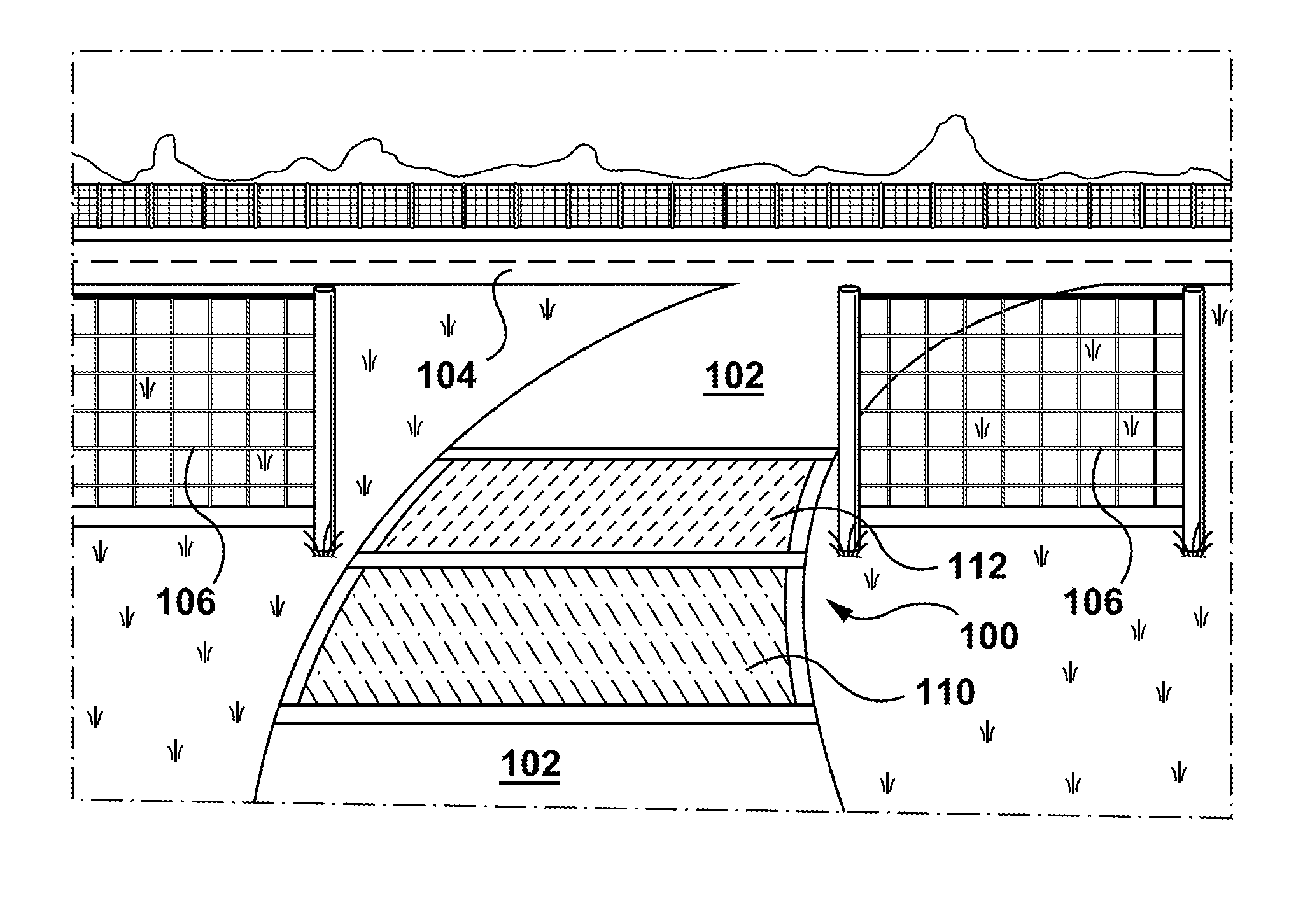
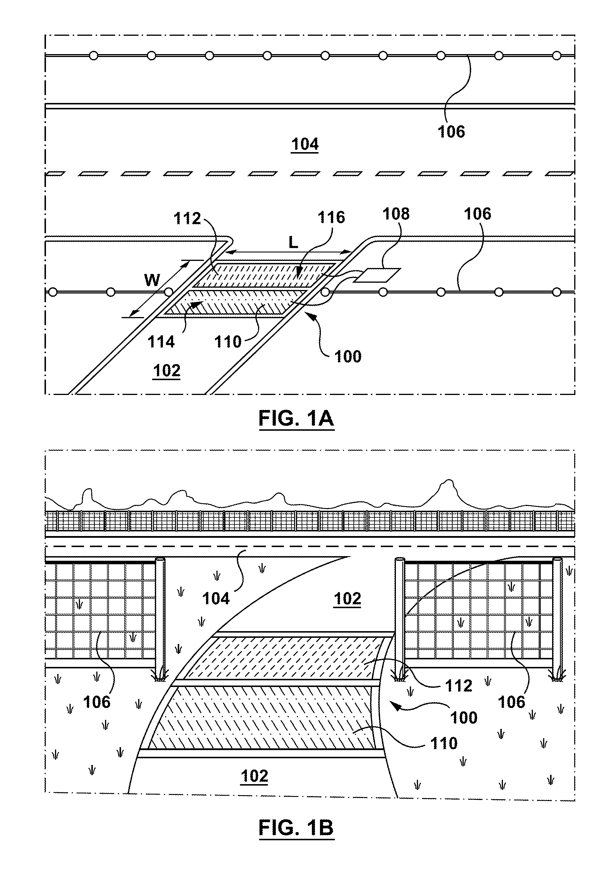
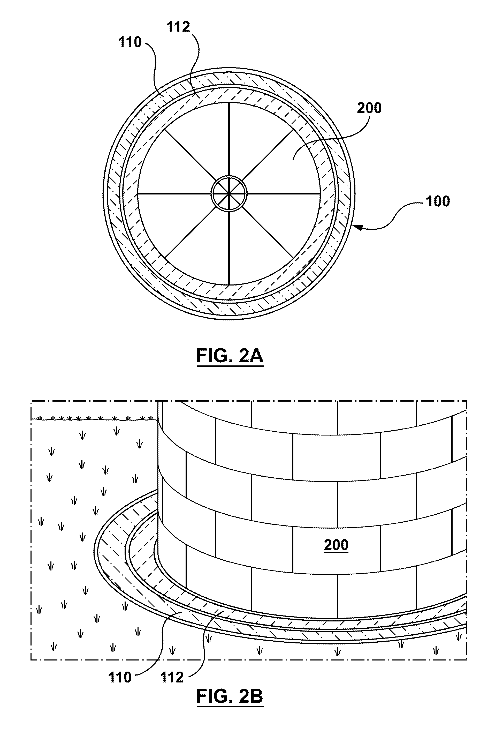
[0090]Step 1: Preparation of the primary mixer for the composition used to form conductive elements 110, 112:[0091]A 5 litre Hobart mixer was charged with 600 grams of spherical coke breeze grade 251 (Asbury Carbons, Asbury N.J., USA, hereafter ‘Coke 251’), and 300 grams of Barnes 49 silica sand (Orca Minerals, Waterdown, ON, Canada, hereafter ‘Barnes’), and mixed at low speed for two minutes.

[0092]Step 2: Preparation of the premix:[0093]To a 1 litre beaker on a hot plate was added 60 grams of the curing agent (Epoxy Part B), Jeffamine D-400 (Huntsman Intl., Woodlands Tex., USA), and 100 grams 58-20 grade asphalt cement (Coco Paving, Downsview, ON, Canada, hereafter, ‘58-28’). With a laboratory mixer running the temperature was raised to 159° F., and the components were stirred until the bitumen was fully dissol...

example 2

Electrical Conductivity

[0096]The electrical conductivities of a number exemplars prepared according to the procedure in Example 1, and using various ingredients are given in Table 1. The samples consisted of cylinder 4″ high, and 2″ in diameter. Components include several combinations of carbon sources, mineral fillers (here represented by Barnes sand) and bitumen, and commercially available bis-phenol epoxies and curing agents. The electrical resistance of these various exemplars is given in the right hand column of the table.

Identification of Components:

[0097]‘KER 828’ refers to Epoxy Resin grade KER 828, Kumho P&B Chemicals, Seoul, Korea[0098]‘D-230’ and ‘D-400’ refer to epoxy curing agents Jeffamine D-230 and D-400 (Huntsman Intl., Woodlands Tex., USA) respectively.[0099]‘Resinlab A’ and ‘B’ refer respectively to Epoxy and Curing agents EP parts A and B, marketed by Resinlab, Germantown, Wis., USA.[0100]‘Eponan’ refers to Epoxy Resin from Na Ya Plastics Corp, Taiwan ‘Oxbow’ refe...

example 3

Compressive Strength

[0101]This section provides information on the range of compressive strengths provided by different exemplar formulas. The compressive strengths of a number exemplars using similar sized samples and method used in Example 2, and using various ingredients are given in Table 2. The degree of cure is indicated by the compressive strength in pounds per square inch (PSI). The strength values were determined on 250 ml cylinders using a Schmidt model RL test hammer, and the results presented in the far right hand columns were obtained using two curing regimes. The second last column data were obtained by testing samples which had been cured for two days at ambient temperature, while (70° F.) while those in the last column were subjected to a temperature of 120° F.) for another four days.

TABLE 2IngredientsCokeDowKERResin-Resin-JeffJeffPSIPSIFormula251Oxbow58-28Barnes331828EponanLab ALab B23040070° F.120° F.3 / 12-I7022.57.5380056003 / 12-II80155475060003 / 12-III30303010150048...


PUM

PropertyMeasurementUnit
compressive strengthaaaaaaaaaa
voltageaaaaaaaaaa

Abstract

An animal exclusion system comprising first and second conductive elements electrically isolated from each other and each having a different electrical potential applied thereto, the first and second conductive elements each comprising carbonaceous particles in a polymeric binder forming a conductive load bearing surface, the load bearing conductive surface of the first conductive element being close enough to the load bearing conductive surface of the second conductive element for both surfaces to simultaneously be in electrical contact with an animal of predetermined size.

Description

[0001]This application claims priority to and the benefit of U.S. Patent Application No. 61 / 976,728 filed Apr. 8, 2014, the contents of which are incorporated herein by reference.BACKGROUND[0002]This disclosure relates to systems and methods used to control the movement of domestic and wild animals, including systems and methods that make use of electrical conductors. It is known to control the movement of wild and domestic animals by the installation of metallic and non-metallic conductors including electric fences, electrically conductive plates or mats. Prior systems may suffer from a number of shortcomings which include:[0003]I. inflexible installation limited to certain applications and certain target species;[0004]II. difficulty of construction;[0005]III. inability to withstand a wide range of climatic conditions including snow storms or heavy rains;[0006]IV. being prone to corrosion, material decomposition and other decay;[0007]V. the inability to discourage wildlife from att...

Claims


Application Information

Patent Timeline
Patent Type & Authority Applications(United States)
IPC IPC(8): A01M29/24H01B1/24A01M29/30E01C11/26A01K3/00
CPCE01C11/265A01K3/002A01M29/24H01B1/24A01M29/30A01K3/004
Inventor LAMPMAN, RICHARDTRUELOVE, BRADSIROLA, TODDHAGENS, GRAHAM
Owner LAMPMAN WILDLIFE MANAGEMENT SERVICES
Why Eureka
Try Eureka