Parameter derivation method

a parameter and derivation method technology, applied in the direction of impedence measurement, resistance/reactance/impedence, instruments, etc., can solve the problems of labor and time, inability to know the coupling capacitance and coupling coefficient, and sometimes large measurement errors, so as to facilitate the design of the shape and size of the electrode and achieve the effect of small measurement errors and easy derivation

Active Publication Date: 2015-10-08
MURATA MFG CO LTD
View PDF1 Cites 6 Cited by
  • Summary
  • Abstract
  • Description
  • Claims
  • Application Information

AI Technical Summary

Benefits of technology

[0017]In addition, by deriving the capacitances C1, C2 and C3, design of the shape and size of the electrodes becomes easier compared with the case where the electrodes are repeatedly designed using a so-called “cut and try” process to obtain desired capacitive coupling. In addition, even if the value of the coupling capacitance is very small, the measurement error can be made small compared with the case where the parameters of the capacitive coupling unit are measured by disconnecting the electrodes and the circuit.

Problems solved by technology

However, in the configuration described in Patent Document 1, although the capacitance generated between the electrodes can be made large, the coupling capacitance and coupling coefficient are not known and suitable values for these parameters are not known.
Consequently, it is necessary to repeatedly design the active electrodes and the passive electrodes using a so-called “cut and try” process and therefore labor and time are needed.
In addition, in power transmission systems, to date, because the values of coupling capacitances are very small, when a coupling unit has been directly measured, parasitic capacitances generated between the coupling unit and, for example, the probe of a measurement instrument have had an effect and measurement errors have sometimes become large.
Consequently, in order to derive the necessary parameters, the necessary parameters have been measured in a state where a transformer unit and the coupling unit are isolated from each other, but in this case there is a problem in that errors are generated in the derived parameters and as a result power transmission cannot be performed with an optimum power transmission efficiency with the final devices that have the transformer units and the coupling unit incorporated therein.

Method used


Image

  • Parameter derivation method
  • Parameter derivation method
  • Parameter derivation method

Examples


Embodiment Construction

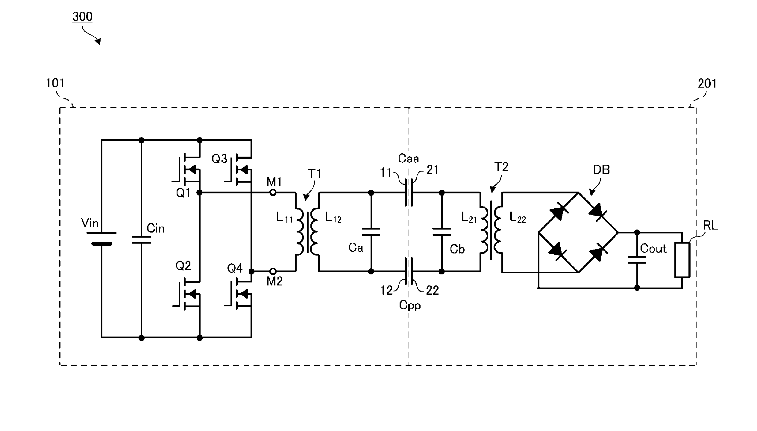
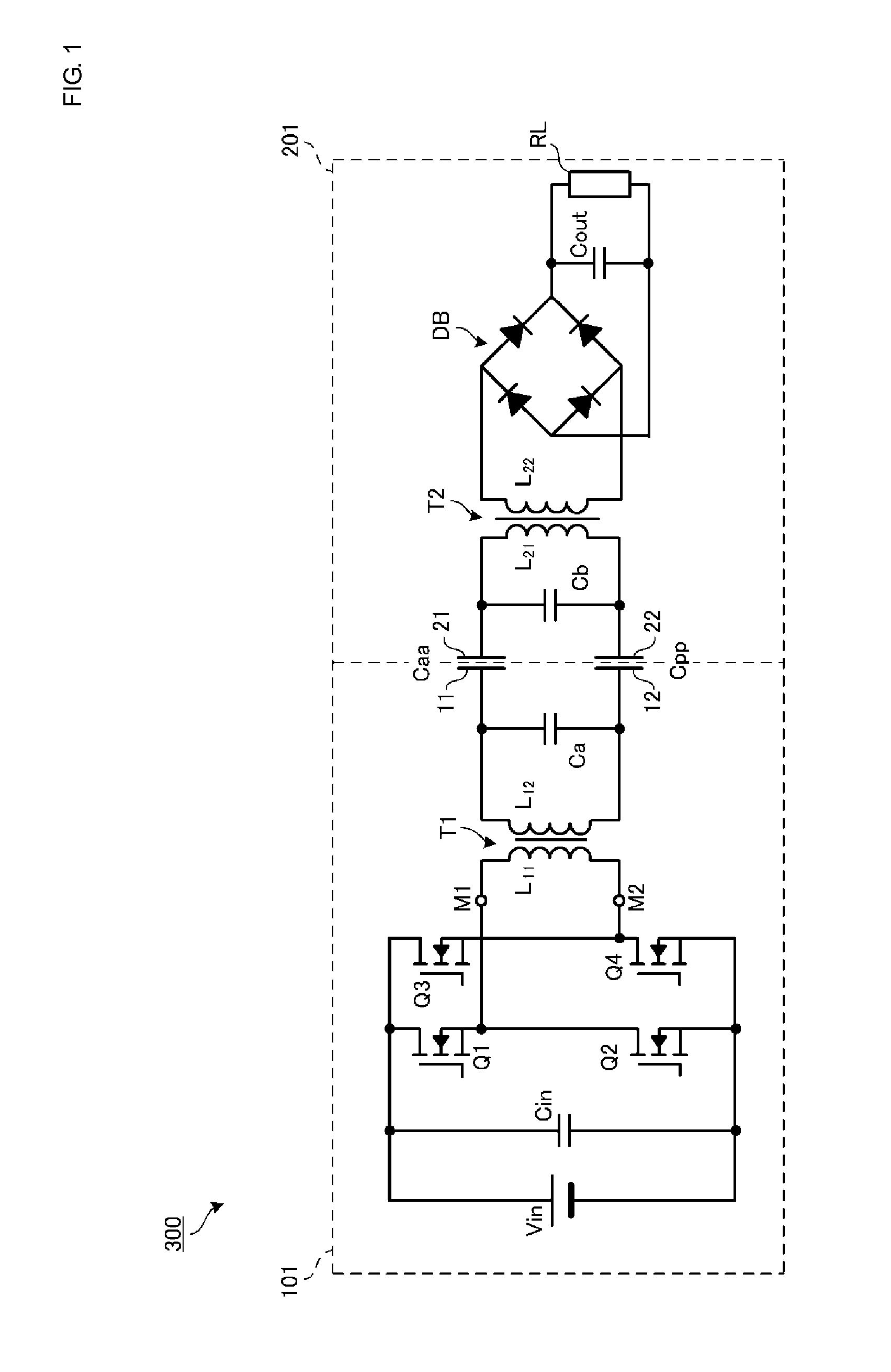
[0023]FIG. 1 is a circuit diagram of a wireless power transmission system 300 according to an embodiment. The wireless power transmission system 300 includes a power transmission device 101 and a power reception device 201. The power reception device 201 includes a load RL. The load RL is a battery module that includes a rechargeable battery and a charging circuit. The power reception device 201 is for example a mobile electronic appliance equipped with a rechargeable battery. Examples of such a mobile electronic appliance include cellular phones, PDAs, portable music players, laptop PCs, digital cameras and so forth. The power reception device 201 is mounted on the power transmission device 101 and the power transmission device 101 charges the rechargeable battery of the power reception device 201.

[0024]The power transmission device 101 includes a direct current power supply Vin that outputs DC 5V or 12V. An input capacitor Cin is connected to the direct current power supply Vin. I...


PUM


Abstract

A method for determining parameters of a wireless power transmission system is disclosed where the wireless power transmission system transmits power from a power transmission device to a power reception device via electric field coupling. The parameters include a coupling coefficient ke of an electric field coupling unit that is formed of active electrodes and passive electrodes of the power transmission device and the power reception device.

Description

CROSS REFERENCE TO RELATED APPLICATIONS[0001]The present application is a continuation of PCT / JP2013 / 084008 filed Dec. 19, 2013, which claims priority to Japanese Patent Application No. 2013-026486, filed Feb. 14, 2013, the entire contents of each of which are incorporated herein by reference.FIELD OF THE INVENTION[0002]The present invention relates to a parameter derivation method for deriving parameters related to electric field coupling in an electric-field-coupling-scheme wireless power transmission system.BACKGROUND OF THE INVENTION[0003]As an example of a wireless power transmission system, the electric-field-coupling-scheme wireless power transmission system described in Patent Document 1 is known. In this system, an active electrode and a passive electrode of a power transmission device and an active electrode and a passive electrode of a power reception device are brought close to each other with a gap therebetween, whereby the pairs of electrodes become capacitively couple...

Claims


Application Information

Patent Timeline
Patent Type & Authority Applications(United States)
IPC IPC(8): G01R21/07G01R23/07H02J5/00
CPCG01R21/07G01R23/07H02J5/005H02J7/025G01R27/02H04B5/0037H02J50/05G01R27/18G01R21/06
Inventor ICHIKAWA, KEIICHI
Owner MURATA MFG CO LTD
Why Eureka
Try Eureka