Optical diffusing films and methods of making same

a technology of optical diffusing films and optical film, applied in the field of optical film, can solve the problems of unwanted abrasion in the system, bead films are also susceptible to crossweb, lot-to-lot variability, and add to the cost of manufacture, and achieve the effect of reducing the average roughness and topography, and high average roughness

Active Publication Date: 2015-10-15
3M INNOVATIVE PROPERTIES CO
View PDF3 Cites 26 Cited by
  • Summary
  • Abstract
  • Description
  • Claims
  • Application Information

AI Technical Summary

Benefits of technology

[0006]We have developed a family of optical diffusing films, and methods of making such films, that can overcome one, some, or all of the foregoing difficulties or challenges. The films can be made by fabricating a tool having a structured surface, and microreplicating the structured surface as a major surface of the optical film. Fabrication of the tool can involve electrodepositing a first layer of a metal under conditions that produce a first major surface with a relatively high average roughness, followed by covering up the first layer by electrodepositing a second layer of the same metal on the first layer, under conditions that produce a second major surface with a relatively lower average roughness, i.e., lower than that of the first major surface. The second major surface has a structured topography which, when replicated to form a structured major surface of an optical film, provides the film with a desired combination of optical haze and optical clarity, along with other characteristics related to the topography of the structured surface that can be advantageous when the film is combined with other components in a display, e.g. for avoiding artifacts such as moire, sparkle, graininess, and / or other observable spatial patterns or marks. Before microreplication, the second major surface may be further treated, e.g., coated with a thin layer of a different metal such as for purposes of passivation or protection, but such a coating is preferably thin enough to maintain substantially the same average roughness and topography as the second major surface of the second layer. By forming the structured surface using electrodeposition techniques rather than techniques that require cutting of a substrate with a diamond tool or the like, large area tool surfaces can be prepared in substantially less time and at reduced cost.

Problems solved by technology

In the case of diffusing films having beaded constructions, beads add to the cost of manufacture.
Beaded films are also susceptible to downweb, crossweb, and lot-to-lot variability.
Furthermore, individual beads can dislodge from the film, e.g. when cutting or converting the film into individual sheets, and the dislodged beads may cause unwanted abrasion in the system of which the diffusing film is a part, e.g. a display or backlight.
Feature sizes averaging less than about 15 or 10 microns are desirable in order to avoid an optical artifact known as “sparkle” or granularity when the film is used in modern display systems, and the time required to cut a tool having such small feature sizes for Type I Microreplicated diffusing films can become long or excessive, and can increase manufacturing costs.
In the case of Type II Microreplicated diffusing films, although the manufacturing process can be tailored to provide films with various levels of optical haze, the optical clarity of such films tends to be relatively high (e.g. in comparison to Type I Microreplicated diffusing films), which is sometimes considered disadvantageous because, for a given amount of optical haze, a diffusing film with a higher optical clarity does not hide defects as well as a similar film with a lower optical clarity.
In the case of microreplicated diffusing films in which a structured surface is made using a sandblasting procedure, such films tend to have detectable spatial non-uniformities, e.g., patterns or artifacts that are the result of the path taken by the sandblasting jet or nozzle as it scans across the extended surface of the tool.
Furthermore, the structured surface may comprise discernible structures, e.g. in the form of distinct cavities and / or protrusions, and the structures may be limited in size along two orthogonal in-plane directions.

Method used


Image

  • Optical diffusing films and methods of making same
  • Optical diffusing films and methods of making same
  • Optical diffusing films and methods of making same

Examples


examples

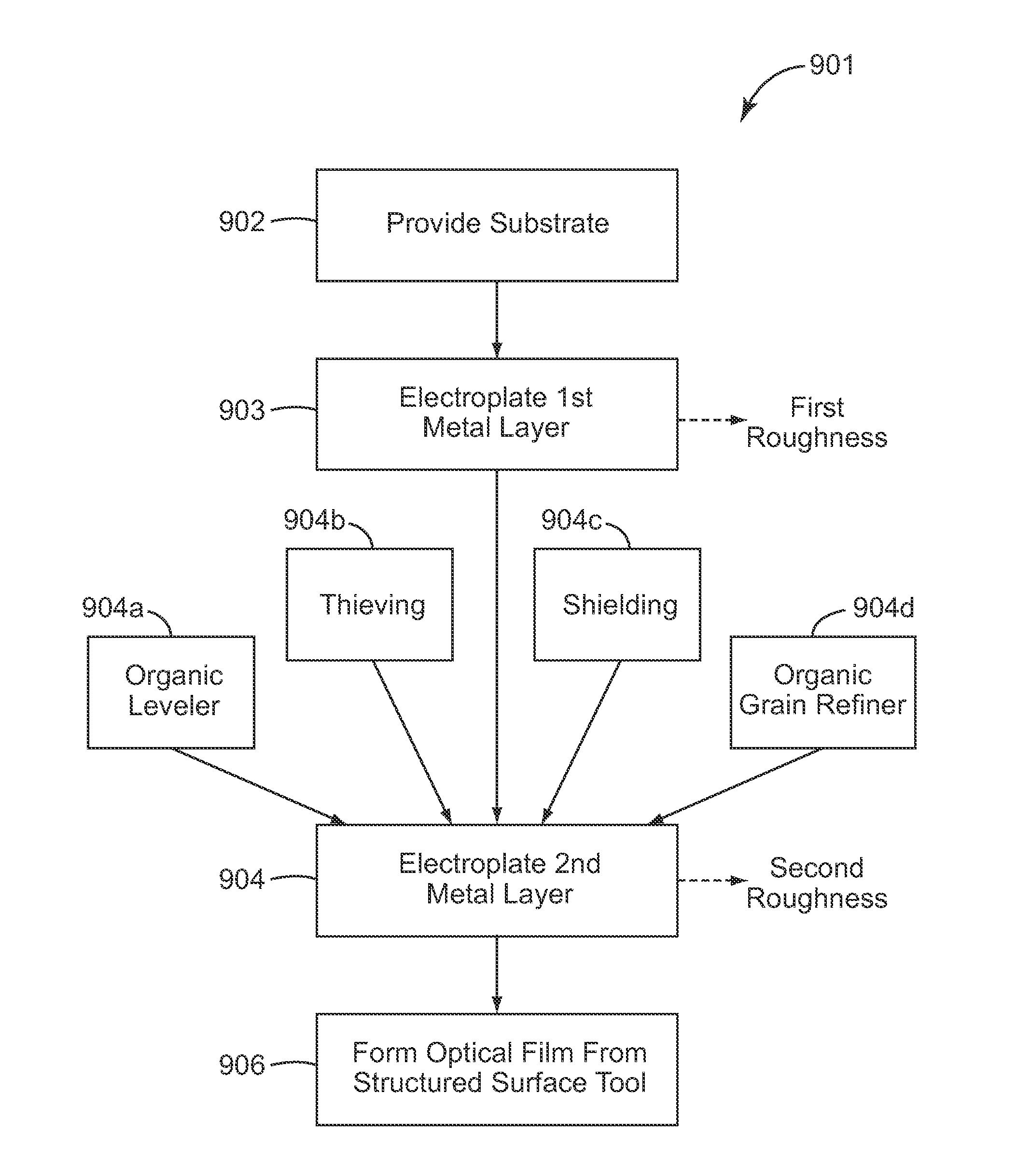
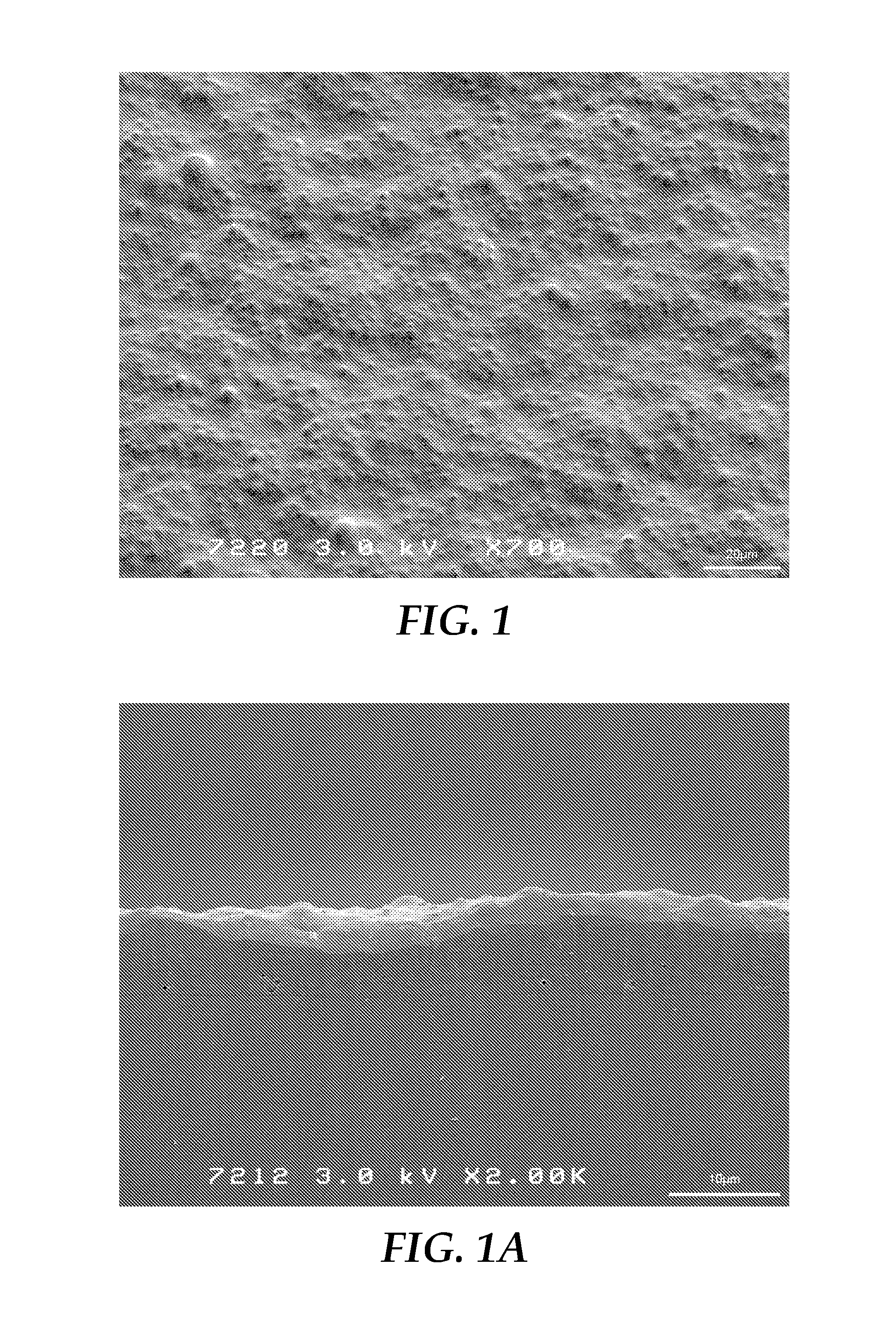
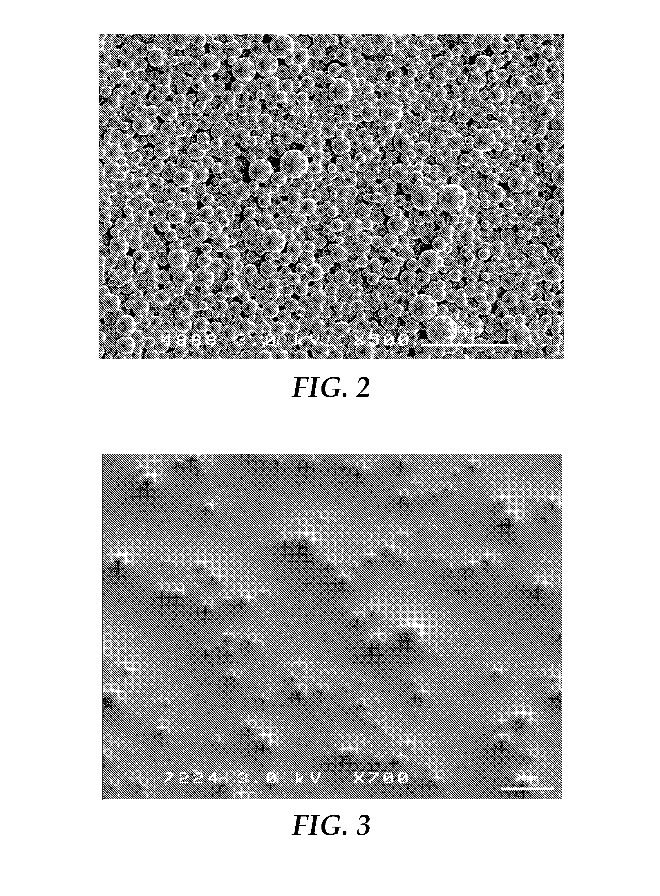
[0110]A number of optical diffusing film samples were made according to methods as shown in FIG. 9. Thus, in each case, a structured surface tool was made under a set of process conditions, and then the structured surface of the tool was microreplicated to form a corresponding structured surface (in inverted form) as a major surface of the optical film. (The opposed major surface of each optical film was flat and smooth.) The structured surface provided each optical film with a given amount of optical haze and optical clarity. The haze and clarity of each optical diffusing film sample was measured with the Haze-Gard Plus haze meter from BYK-Gardiner. The following table sets forth some of the chemical solutions that were used during the fabrication of various samples, as explained further below:

TABLE 1Some Solutions UsedElementComponentSupplierQuantityAlkaline cleaner25% Sodium hydroxideHawkins Chemical30% v / v(NaOH)(Minneapolis, MN)16% Sodium carbonateHawkins Chemical3.5% v / vTriton ...


PUM

PropertyMeasurementUnit
aspect ratioaaaaaaaaaa
optical hazeaaaaaaaaaa

Abstract

Optical diffusing films are made by microreplication from a structured surface tool. The tool is made using a 2-part electroplating process, wherein a first electroplating procedure forms a first metal layer with a first major surface, and a second electroplating procedure forms a second metal layer on the first metal layer, the second metal layer having a second major surface with a smaller average roughness than that of the first major surface. The second major surface can function as the structured surface of the tool. A replica of this surface can then be made in a major surface of an optical film to provide light diffusing properties. The structured surface and/or its constituent structures can be characterized in terms of various parameters such as optical haze, optical clarity, Fourier power spectra of the topography along orthogonal in-plane directions, ridge length per unit area, equivalent circular diameter (ECD), and/or aspect ratio.

Description

FIELD OF THE INVENTION[0001]This invention relates generally to optical films, with particular application to such films that can be made by microreplication from a tool, and where the tool may be readily tailored to provide the film with a controlled amount of optical diffusion and optical clarity with exceptional spatial uniformity.BACKGROUND[0002]Display systems, such as liquid crystal display (LCD) systems, are used in a variety of applications and commercially available devices such as, for example, computer monitors, personal digital assistants (PDAs), mobile phones, miniature music players, and thin LCD televisions. Many LCDs include a liquid crystal panel and an extended area light source, often referred to as a backlight, for illuminating the liquid crystal panel. Backlights typically include one or more lamps and a number of light management films such as, for example, light guides, mirror films, light redirecting films (including brightness enhancement films), retarder fi...

Claims


Application Information

Patent Timeline
Patent Type & Authority Applications(United States)
IPC IPC(8): G02B5/02C25D5/16C25D3/04C25D5/12B29C59/02C25D3/38
CPCG02B5/021B29C59/026C25D3/38B29L2011/00C25D5/12C25D5/16G02B5/0268C25D3/04G02B5/0221G02B5/0278G02B6/0051G02F1/133606C25D5/605C25D5/627B30B15/062
Inventor PHAM, TRI D.KONG, STEVEN H.ZHANG, HAIYANARONSON, JOSEPH T.LEAF, MICHAEL R.BOYD, GARY T.JOHNSON, NICHOLAS A.WANG, QINGBING
Owner 3M INNOVATIVE PROPERTIES CO
Why Eureka
Try Eureka