Grid Level Flywheel Electric Storage System

a technology of electric storage system and flywheel, which is applied in the direction of mechanical power/torque control, level control, instruments, etc., can solve the problems of power available requires enormous waste of resources, and the use of a multitude of users suffers from varying load demand, etc., to achieve the effect of increasing the power level of the grid or wind generated outpu

Inactive Publication Date: 2015-10-15
SIMONS GERALD FR
View PDF5 Cites 4 Cited by
  • Summary
  • Abstract
  • Description
  • Claims
  • Application Information

AI Technical Summary

Benefits of technology

[0029]If energy is to be derived from Flywheel 46, Flywheel motor pump 44 is configured by Flywheel directional control valve 42 to function as a pump and pump hydraulic energy into the system ultimately increasing the power level of the grid or wind generated output. If energy is to be added to the storage level of Flywheel 46, Flywheel directional control valve 42 configures Flywheel hydraulic motor pump 44 to function as a motor. Hydraulic energy derived from the system is fed to Flywheel hydraulic motor pump 44 causing the speed of Flywheel 46 to increase thus storing the added energy in Flywheel 46.

Problems solved by technology

Electrical power distributed by the electric grid, for usage by a multitude of users suffers from varying load demand.
The utility is obligated to service the load at all times. To have that power available requires an enormous waste of resources.
Renewable sources of energy are being exploited but their contribution is limited to times when the sun shines or when the wind blows.
Prior art to resolve the need for electrical storage systems is limited to two general areas.
In practice, that is not practical but has been done in cases where grid support is mandatory.
They are expensive to buy.
They begin to deteriorate immediately when placed in service and therefore must be replaced in a very short time.
That limits their life to slightly more than year.
In some battery types, large discharge currents cause internal heating to the point that the battery explodes.
The energy that can be derived from a battery is limited to a small fraction of its storage capability.
Nickel metal hydride batteries are only slightly better and cost much more.
The failure mode of batteries is to develop a short circuit between the positive and negative terminal.
That current develops sufficient heat to cause the battery to explode with a potential ensuing fire.
Not only is there a danger from the explosion, the entire area is exposed to the flying electrolyte, in this case acid.
A major personnel and environmental hazard is the result.
There are many other disadvantages relating to battery storage.
Flywheel energy storage is also used but with limited success.
Electric motors are unable to exert large starting torques.
Thus a stalled, or near stalled motor current reaches enormous magnitude and the motor suffers a heat failure.
The resulting flywheel is therefore small, light weight and runs at a high speed limited by its structural hoop stress ability and motor stall characteristics.
The energy stored in the flywheel is a function of its moment of inertia that is a function of the square of its radius, thus making the flywheel small reduces its storage capability.
To maximize the storage capability and still meet the allowable hoop stress limitation, materials used in flywheels have been improved but still the typical commercially available flywheel stores a minimum, nearly impractical amount of energy.
Ultimately the entire energy recovery system is limited by magnetic saturation.
To synchronize the flywheel to the electric grid because of the high frequency of its output is exceptionally difficult.
A major concern with existing flywheels is the danger of explosion that would occur upon a structural failure.

Method used


Image

  • Grid Level Flywheel Electric Storage System
  • Grid Level Flywheel Electric Storage System

Examples


Embodiment Construction

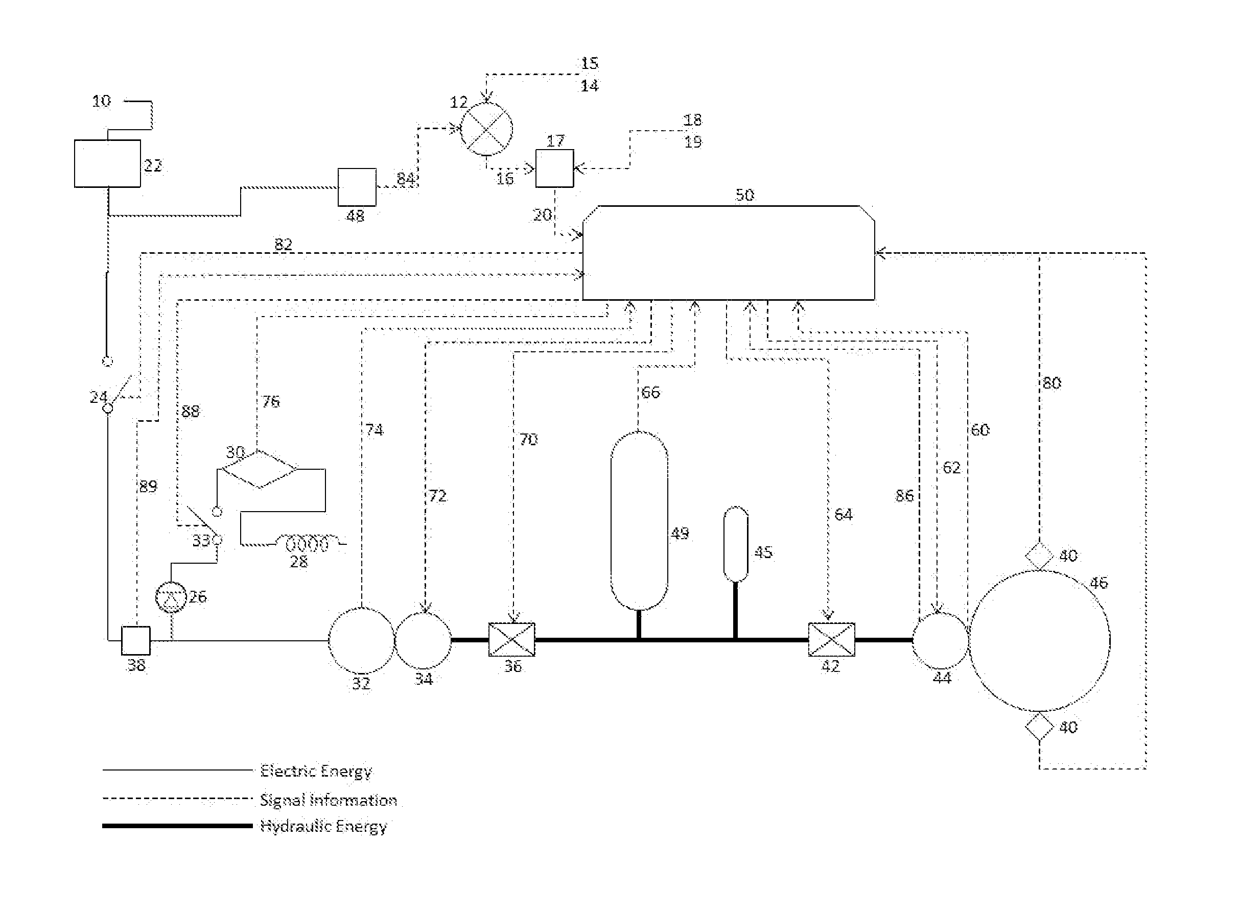
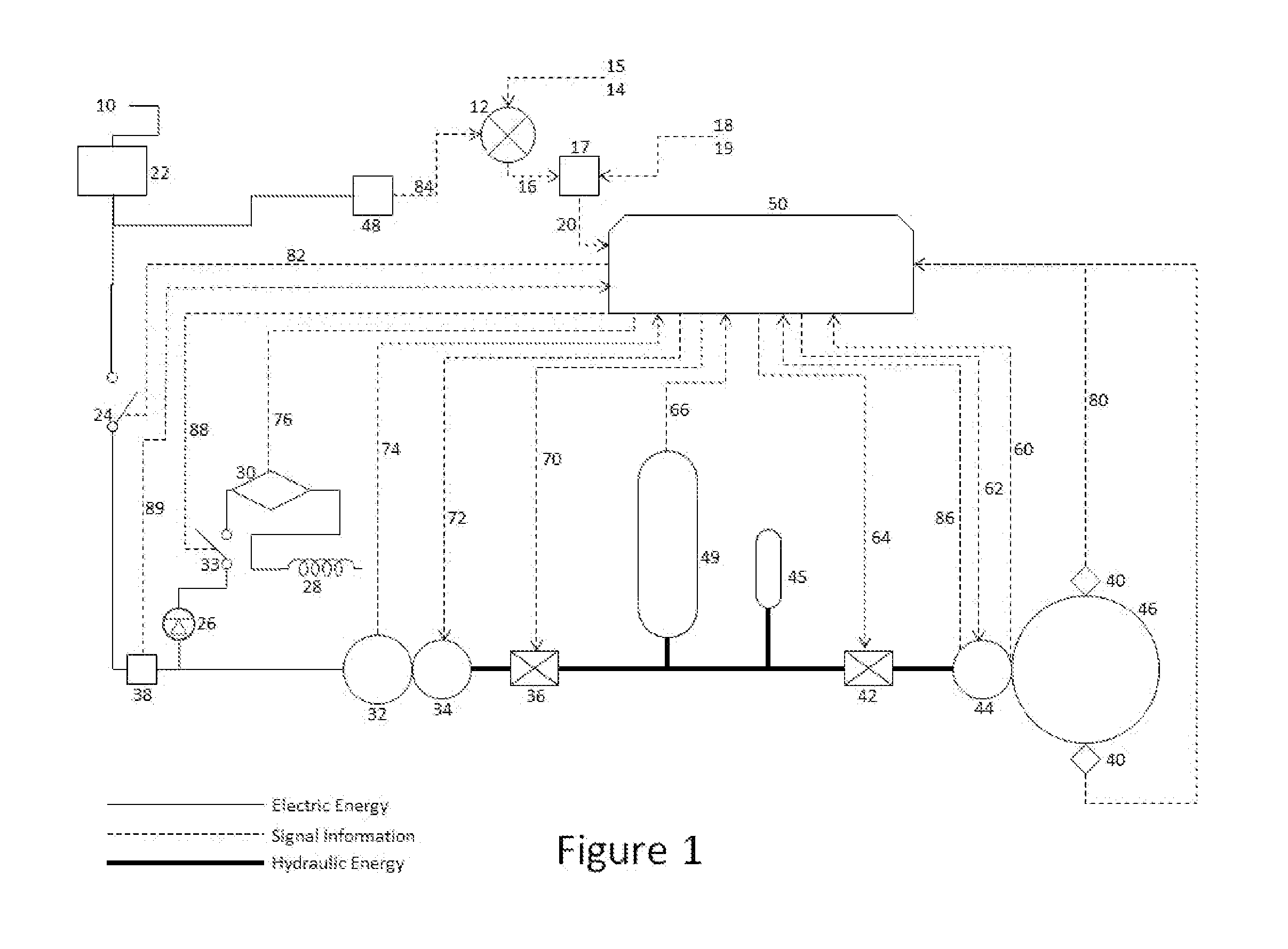
[0016]FIG. 1 shows a functional block diagram of the system. It is understood that the form of the electrical power is typically 3 phase with appropriate grounding and neutral conductors. FIG. 1 is a line diagram showing the system functions.

[0017]The power level and frequency of the electrical grid serving the US or another segment of the globe varies with the applied load. Further it varies from one region to another. Additionally, the level of power generated by renewable energy systems such as wind farms and photovoltaic arrays depend upon the vagaries of nature. The wind does not always blow nor at the same speed. The sun does not always shine with the same intensity. Power storage or frequency control becomes a necessity in order to maintain a required level of power and the correct frequency to serve the loads

[0018]The generators that supply the grid produce power to the grid at a fixed frequency and voltage. Those parameters are controlled by governors on the generators at t...


PUM


Abstract

An Electrical Energy Storage system to store power generated at times of surplus availability of power in the grid or wind derived generator and stored as energy in a flywheel for use at times of grid or wind generated power shortage. The system is based upon computer control of power being processed by hydraulic components into storage provided by a conventional flywheel being hydraulically driven and harvested by means of converting hydraulic energy into electrical energy. Energy for storage may be derived from the national electric grid, any renewable energy source, or other electrical source. The energy stored in the flywheel may be harvested and returned to the grid or any other electrical sink.

Description

CROSS REFERENCE TO RELATED APPLICATIONS[0001]This application claims the benefit of Provisional Patent Application No. 61 / 853,760STATEMENT REGARDING FEDERALLY SPONSORED RESEARCH AND DEVELOPMENT[0002]Not applicableBACKGROUND OF THE INVENTIONField of the Invention (Technical Field)[0003]The present invention relates to electrical storage systems, specifically electrical storage systems that provide the provisions for stabilization and energy management of the electric grid.Brief Summary of the Invention[0004]The embodiment of the present invention is a system comprised of hydraulic, electrical and electronic component parts interconnected to manage the functional capability of a flywheel to control application of flywheel energy storage to provide means to ensure electric grid functional operation.BACKGROUND OF THE INVENTIONPrior Art[0005]Electrical power distributed by the electric grid, for usage by a multitude of users suffers from varying load demand. At different times of the day...

Claims


Application Information

Patent Timeline
Patent Type & Authority Applications(United States)
IPC IPC(8): G05F1/66
CPCG05F1/66
Inventor SIMONS, GERALD FRANK
Owner SIMONS GERALD FR
Why Eureka
Try Eureka