Amplifier circuit with overshoot suppression
an amplifier circuit and suppress scheme technology, applied in the field of amplifier circuits, can solve problems such as abnormal operation of back circuits to receive signals, unstable signals, overshoots in output voltage, etc., and achieve the effect of suppressing overshoots
- Summary
- Abstract
- Description
- Claims
- Application Information
AI Technical Summary
Benefits of technology
Problems solved by technology
Method used
Image
Examples
first embodiment
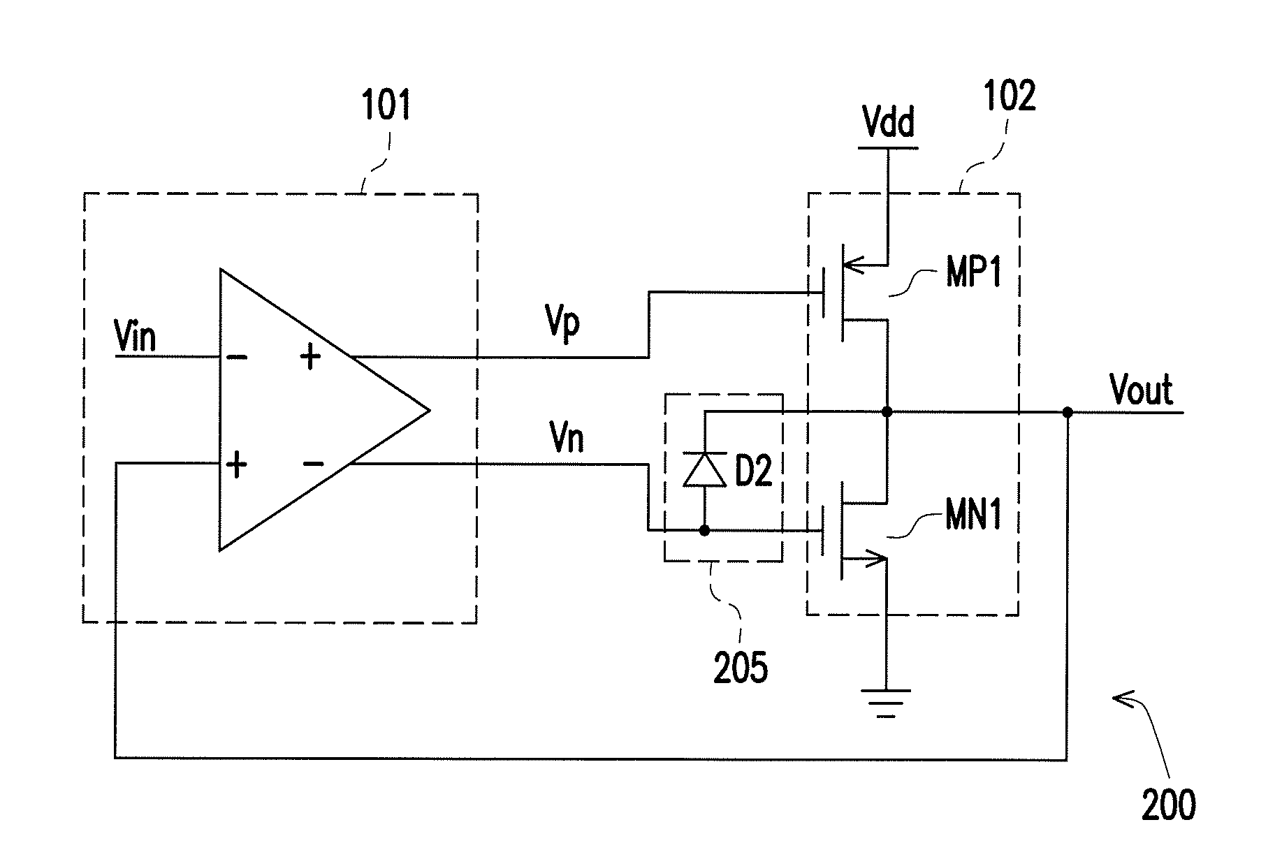
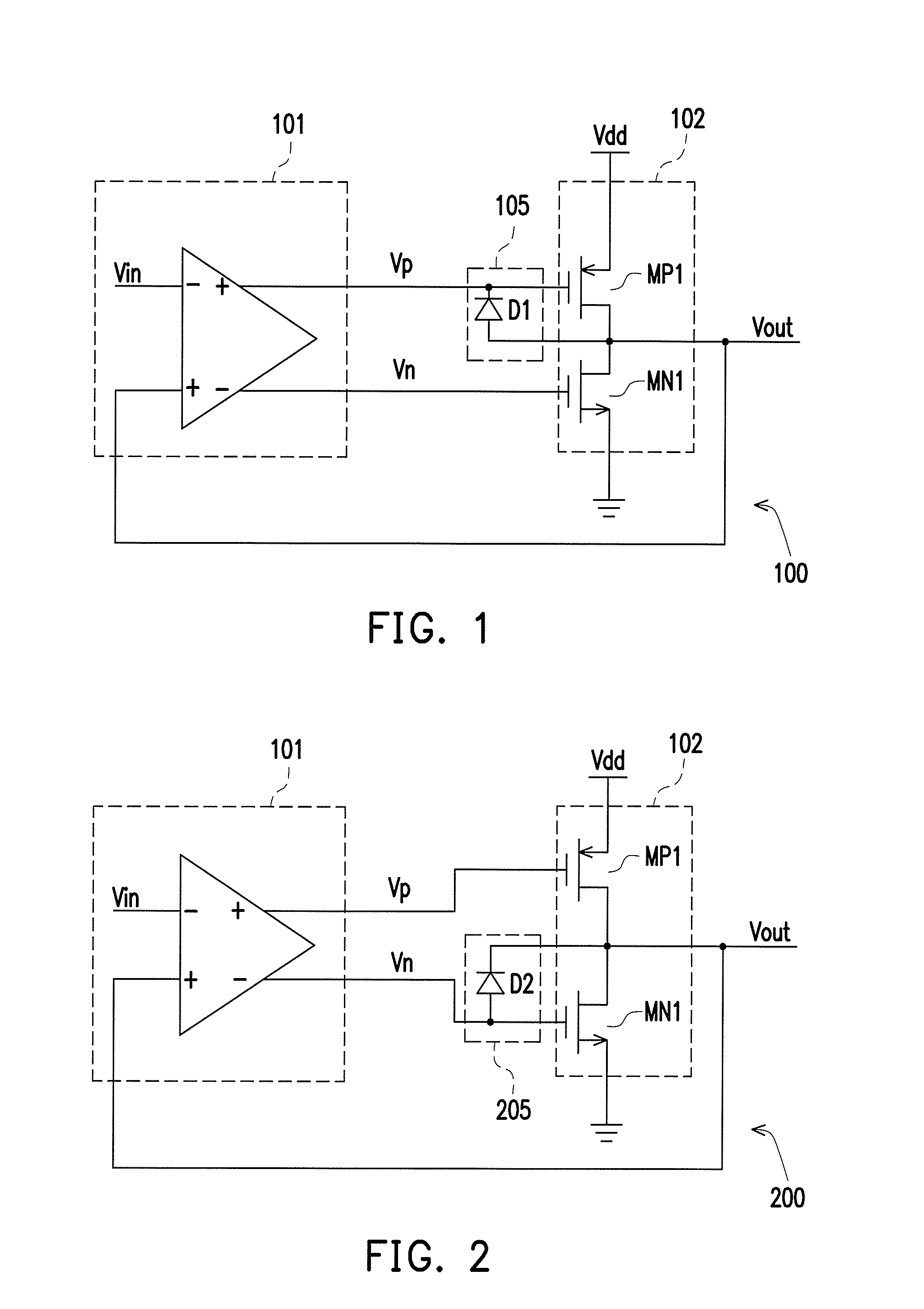
[0052]FIG. 1 is a schematic view of an amplifier circuit with an overshoot suppress scheme according to the invention. Referring to FIG. 1, the amplifier circuit 100 includes an input amplifier 101, an output amplifier 102, and a first diode device 105. In the present embodiment, the input amplifier 101 has a first input end, a second input end, and an output pair. The output amplifier 102 has a first input end, a second input end, and an output end. The first and the second input ends of the output amplifier 102 are respectively coupled to the output pair of the input amplifier 101, and the output end of the output amplifier 102 provides the output voltage Vout.
[0053]A first end of the first diode device 105 is coupled to the output end of the output amplifier 102, and a second end of the first diode device 105 is coupled to the first input end of the output amplifier 102. When a voltage difference between the output end of the output amplifier 102 and the first input end of the ou...
third embodiment
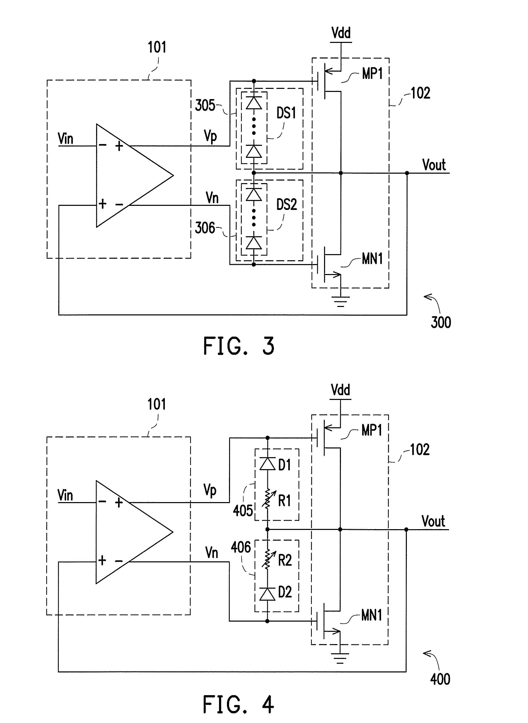
[0066]Herein, another embodiment of the invention is provided. FIG. 3 is a schematic view of an amplifier circuit with the overshoot suppress scheme according to the invention. Referring to FIG. 3, the amplifier circuit 300 with the overshoot suppress scheme is integrated by the amplifier circuits 100 and 200. The implementation of the amplifier circuit 300 may refer to the related illustration of the amplifier circuits 100 and 200. The amplifier circuit 300 has the first diode device 305 and the second diode device 306. The first end of the first diode device 305 is coupled to the output end of the output amplifier 102, and the second end of the first diode device 305 is coupled to the first input end of the output amplifier 102. The first end of the second diode device 306 is coupled to the output end of the output amplifier 102, and the second end of the second diode device 306 is coupled to the second input end of the output amplifier 102.
[0067]In the present embodiment, the fir...
fourth embodiment
[0071]Those who use the present embodiment may add a variable resistor to the diode device to increase the barrier voltage of the diode device as shown in FIG. 4. FIG. 4 is a schematic view of an amplifier circuit with the overshoot suppress scheme according to the invention. Referring to FIG. 4, the implementation of the amplifier circuit 400 may refer to the related illustration of the amplifier circuit 300. The difference of the amplifier circuits 400 and 300 lies in that, a variable resistor is added to each of the first diode device 405 and the second diode device 406. The first diode device has a diode D1 and a variable resistor R1. The first end of the variable resistor R1 is coupled to the first end of the diode D1, the second end of the diode D1 serves as one of the first and the second ends of the first diode device 405, and the second end of the variable resistor serves as the other one of the first and the second ends of the first diode device 405. The connection of the ...
PUM
 Abstract
Description
Claims
Application Information
 - R&D
- Intellectual Property
- Life Sciences
- Materials
- Tech Scout
- Unparalleled Data Quality
- Higher Quality Content
- 60% Fewer Hallucinations
Browse by: Latest US Patents, China's latest patents, Technical Efficacy Thesaurus, Application Domain, Technology Topic, Popular Technical Reports.
© 2025 PatSnap. All rights reserved.Legal|Privacy policy|Modern Slavery Act Transparency Statement|Sitemap|About US| Contact US: help@patsnap.com


