
Arrangement and method for identifying and compensating nonlinear vibration in an electro-mechanical transducer

a nonlinear vibration and electromechanical technology, applied in the direction of frequency response correction, electrical apparatus, deaf-aid sets, etc., can solve the problems of increasing the amplitude of the relationship between forces and displacement, increasing the spectral component (harmonic and intermodulation distortion), and affecting the quality of the sound reproduced by audio devices and the performance of actives. , to achieve the effect of improving the constructional design

Active Publication Date: 2015-10-15
KLIPPEL WOLFGANG
View PDF3 Cites 147 Cited by
  • Summary
  • Abstract
  • Description
  • Claims
  • Application Information

AI Technical Summary

Benefits of technology

This patent describes a way to improve the behavior of electro-mechanical or electro-acoustical transducers by changing their construction or by using inverse nonlinear processing to compensate for distortion. The invention uses a physical model that takes into account the nonlinear excitation of higher modes and the influence of time-varying mode shapes on sound radiation. This method helps to reduce distortion and improve echo cancellation in telecommunication applications.

Problems solved by technology

However, the relationship between forces and displacement becomes nonlinear at higher amplitudes and additional spectral components (harmonic and intermodulation distortion) are generated.
Those distortions impair the quality of the sound reproduced by audio devices and the performance of active noise reduction and echo cancelation.

Method used


Image

  • Arrangement and method for identifying and compensating nonlinear vibration in an electro-mechanical transducer
  • Arrangement and method for identifying and compensating nonlinear vibration in an electro-mechanical transducer
  • Arrangement and method for identifying and compensating nonlinear vibration in an electro-mechanical transducer

Examples


Embodiment Construction

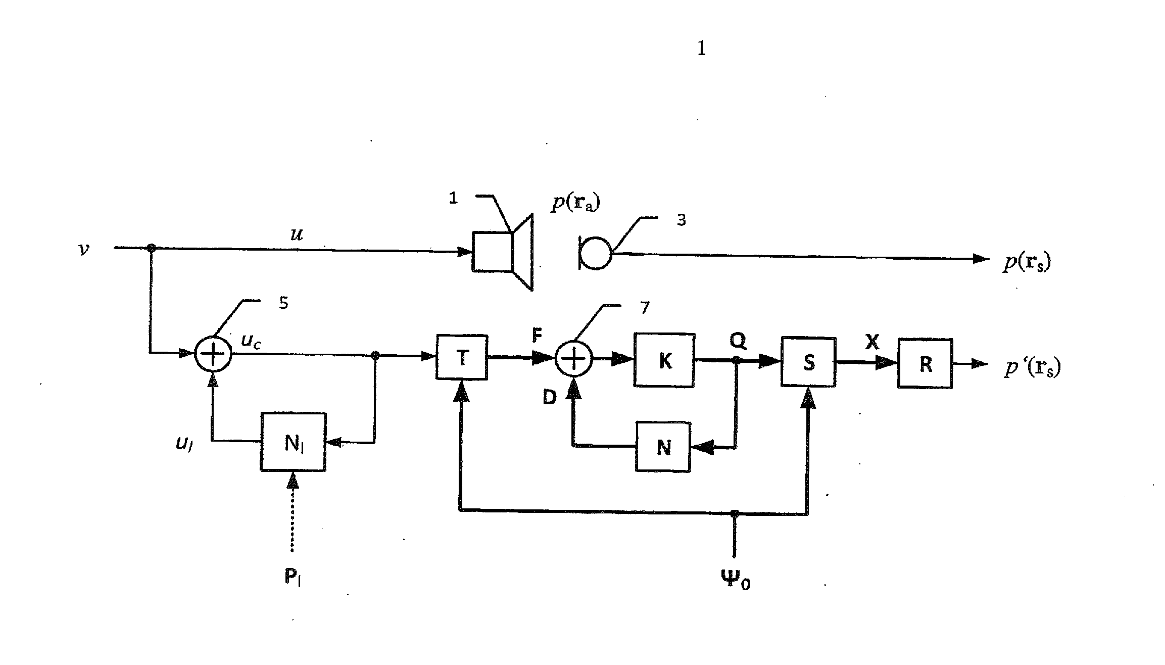
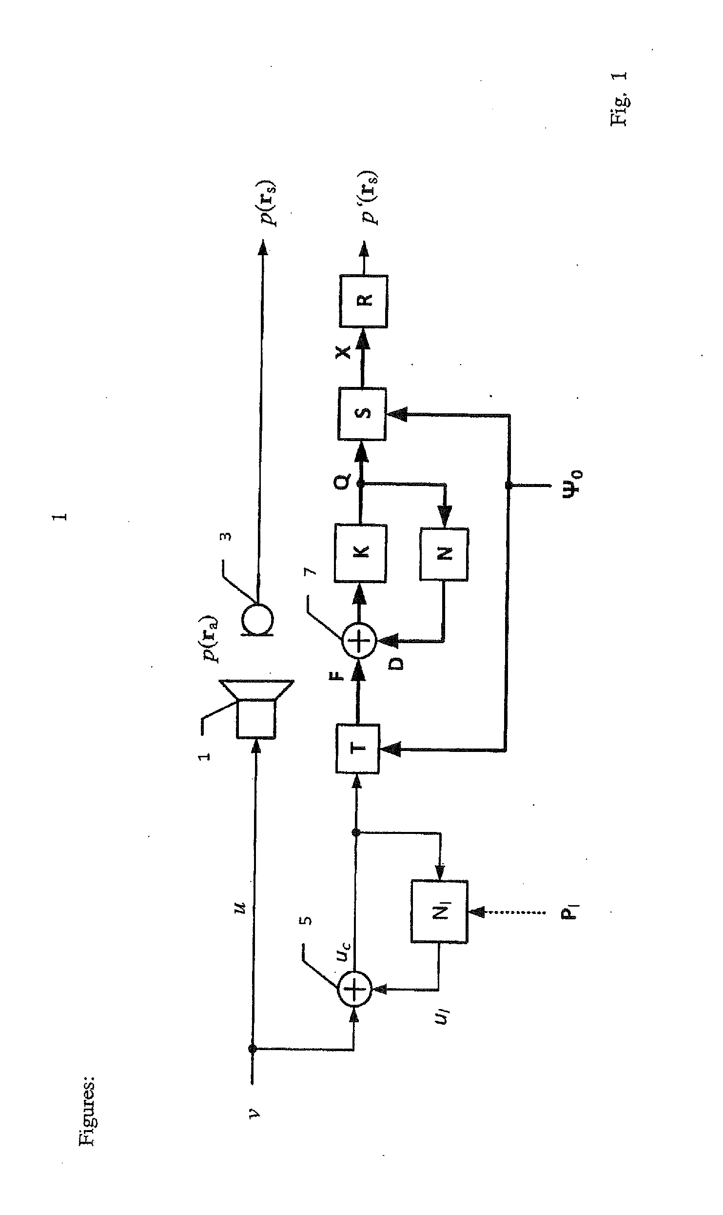
[0038]FIG. 1 shows a first system model describing the transfer behavior of transducer 1 between the electrical input signal v and the sound pressure output signal p(rs) measured by an acoustical sensor 3 at measurement point rs. The nonlinear network model Nl describes the effect of nonlinearities inherent in the motor and in the mechanical suspension of transducer 1 by using lumped parameters Pl and generates a distortion signal ul. The adder 5 generates based on the input signal u and distortion signal ul the distorted input signal uc=u+ul. A modal transformation system T generates based on the distorted input signal uc the excitation forces:

Fm=uc*L-1{BlRe+Les}γm(Ψm(rcoil))m=0,…,M(1)

The forces summarized in vector F=[F0, . . . , Fm, . . . , FM] are generated by the convolution represented by operator * of the distorted input signal uc with the inverse Laplace-transformation L−1{ } of the rational transfer function, comprising force factor Bl, voice coil resistance Re, inductance ...


PUM


Abstract

The invention relates to an arrangement and a method for converting an input signal v into an output signal p(ra) by using an electro-mechanical transducer and for reducing nonlinear total distortion pd in said output signal p(ra), whereas the nonlinear total distortion pd contains multi-modal distortion ud which are generated by nonlinear partial vibration of mechanical transducer components. An identification system generates distributed parameters Pd of a nonlinear wave model (Nd) and lumped parameters Pl of a network model (Nl) based on electrical, mechanical or acoustical state variables of transducer measured by a sensor. The nonlinear wave model distinguishes between activation modes and transfer modes, whereas the activation modes affect the transfer modes, which transfer the input signal u into the output signal p. A control system synthesizes based on the physical modeling and identified parameters Pd and Pl nonlinear distortion signals vd and vl which are supplied with the input signal v to the transducer and compensate for the distortion signals ul and ud generated by the transducer nonlinearities.

Description

FIELD OF THE INVENTION[0001]The invention generally relates to arrangements and methods for converting an input signal into an output signal by using an electro-mechanical transducer and for reducing nonlinear total distortion in said output signal.BACKGROUND OF THE INVENTION[0002]The invention generally relates to arrangements and a methods for identifying parameters of a nonlinear model, which describes the nonlinear vibration of mechanical structures, such as used in electro-mechanical and electro-acoustical transducers. This information is the basis for identifying the constructional causes of the nonlinearities, linearizing the transfer behaviors of those transducers and for compensating actively nonlinear signal distortion in an electrical, mechanical or acoustical output signal.[0003]Loudspeakers and other electro-acoustical transducers use diaphragms, panels, shells and other mechanical structures to generate vibration and sound. At low frequencies the transducer can be mode...

Claims


Application Information

Patent Timeline
IPC IPC(8): H04R3/04
CPCH04R3/04H04R3/08
Inventor KLIPPEL, WOLFGANG
Owner KLIPPEL WOLFGANG
Learn More