Ablation catheter with dedicated fluid paths and needle centering insert

a catheter and fluid path technology, applied in the field of catheters, can solve the problems of steam bubble formation, impedance rise, and limiting current delivery, and not only in tissue heating, and achieve the effect of minimizing the formation of coagulum

Active Publication Date: 2015-10-22
BIOSENSE WEBSTER (ISRAEL) LTD
View PDF2 Cites 7 Cited by
  • Summary
  • Abstract
  • Description
  • Claims
  • Application Information

AI Technical Summary

Benefits of technology

[0011]The catheter of the present invention is directed to an improved catheter with an elongated catheter body, a distal tip section with a tip electrode, a needle electrode assembly configured for longitudinal movement relative to the catheter, and a needle centering insert that is received in a channel formed in the tip electrode. The needle electrode assembly has a proximal tubing and a distal needle electrode, and the insert is advantageously configured to support the needle electrode in the channel of the tip electrode at a predetermined separation distance from the tip electrode while enabling irrigation to flow circumferentially around the needle electrode through the channel and exit at the distal end of the tip electrode for uniform cooling and minimizing the formation of coagulum on the distal end of the tip electrode.
[0012]The catheter also provides a first dedicated pathway that extends through the needle electrode assembly and exits at the distal end of the needle electrode for passing fluid along the catheter and directly into tissue at the needle electrode ablation site. The catheter also provides a second dedicated pathway to supply fluid to the channel in the tip electrode, wherein the second pathway is defined by a guide tube and directed by a plunger member. The guide tube surrounds the needle electrode assembly throughout its length and is sized to provide a gap with an annular cross-section between the inner surface of the guide tube and the outer surface of the proximal tubing. The plunger member is fixedly positioned on the proximal tubing to maintain a fluid-tight seal with the inner surface of the guide tubing for directing the flow distally, as the needle electrode assembly is extended or retracted longitudinally relative to the catheter. To supply fluid to the annular gap, the second pathway includes a traversal from a lumen in the proximal tubing to the annular gap via a hole formed in the sidewall of the proximal tubing. The location of the plunger member on the proximal tubing is immediately proximal of the hole so as to minimize the risk of trapped air bubbles forming in the second pathway. The first and second fluid pathways are advantageously dedicated and independent of each other so as to assure that the fluid passing through each pathway has a constant flow regardless of whether the needle electrode is extended and insert into tissue or retracted into the tip electrode.

Problems solved by technology

Ablation of tissue from an endovascular approach results not only in heating of tissue, but heating of the electrode.
Impedance can then rise and limit current delivery.
Within tissue, overheating can cause steam bubble formation (steam “pops”) with risk of uncontrolled tissue destruction or undesirable perforation of bodily structures.
In cardiac ablation, clinical success is sometimes hampered by inadequate lesion depth and transverse diameter even when using catheters with active cooling of the tip.
Ablation may still be hampered by the small surface area of the needle electrode such that heating occurs at low power, and small lesions are created.
While needle electrodes improve tissue ablation, the structural integrity of a needle electrode may be compromised by steam pops arising from RF “arcing” between the needle electrode and adjacent conductive components of the catheter, including a tip electrode through which the needle electrode extends.
When electrical conduction occurs between the needle electrode and the distal end of the tip electrode, the resulting cavitation or mini-shockwaves produced by the steam pops can cause premature wear and tear on the needle electrode that could lead to breakage and detachment from the catheter.

Method used


Image

  • Ablation catheter with dedicated fluid paths and needle centering insert
  • Ablation catheter with dedicated fluid paths and needle centering insert
  • Ablation catheter with dedicated fluid paths and needle centering insert

Examples


Embodiment Construction

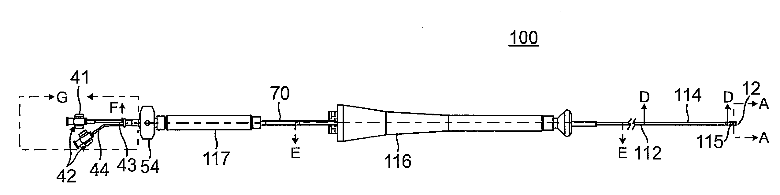
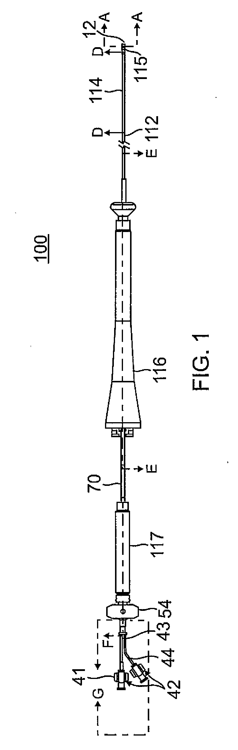
[0044]As shown in FIG. 1, the catheter 100 comprises an elongated catheter body 112, an intermediate deflection section 114, a distal tip section 115, a deflection control handle 116 attached to the proximal end of the catheter body 112, and a needle injector control handle 117 attached indirectly to the catheter body 112 proximal of the deflection control handle 116.

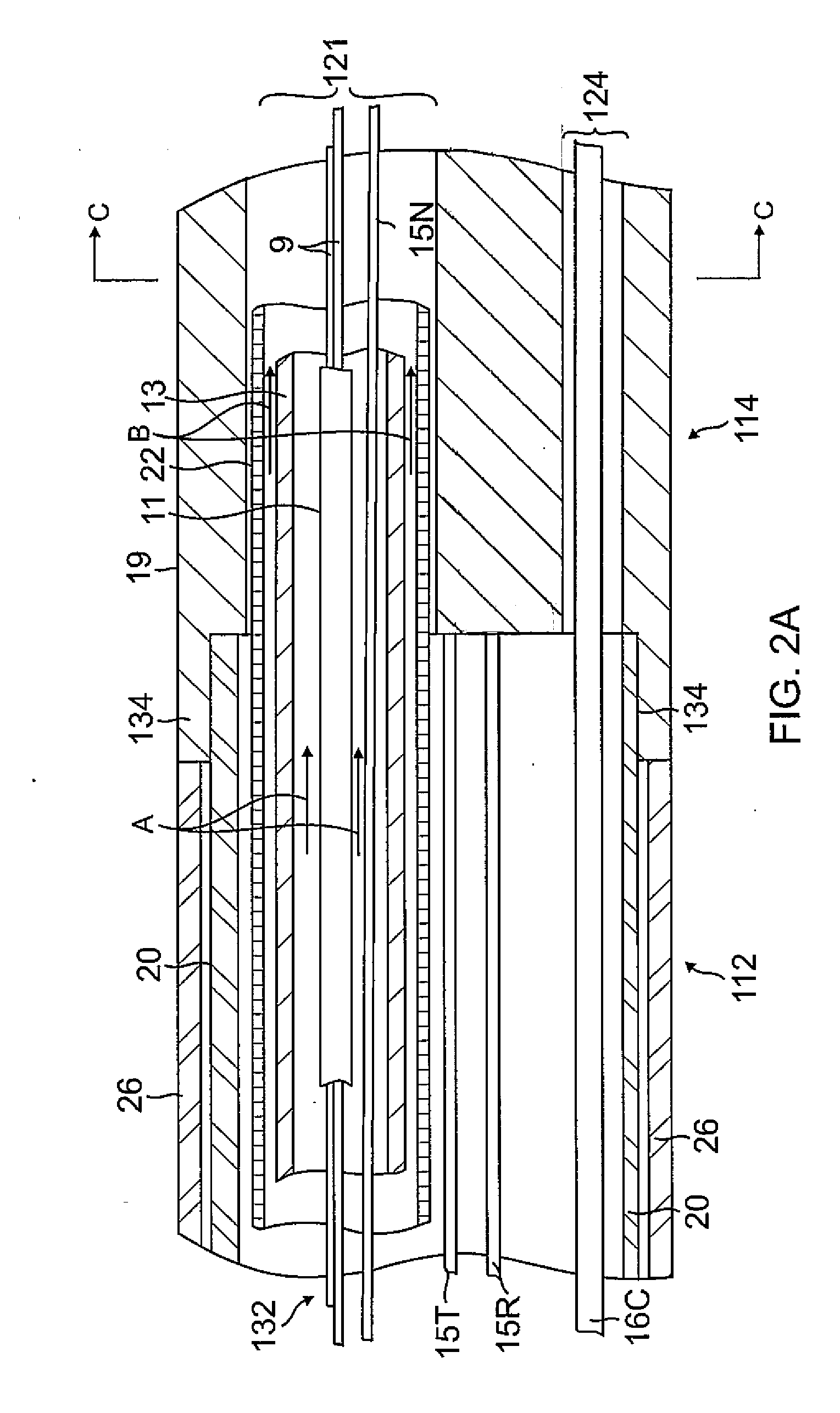
[0045]With reference to FIGS. 2A and 2B, the catheter body 112 comprises a single, central or axial lumen 118. The proximal shaft 112 is flexible, i.e., bendable, but substantially non-compressible along its length. The catheter body 112 may be of any suitable construction and made of any suitable material. In one embodiment, the catheter body 112 comprises an outer wall 26 made of PEBAX®, polyurethane or nylon. The outer wall 26 comprises an imbedded braided mesh of stainless steel or the like to increase torsional stiffness of the catheter body 112 so that, when the deflection control handle 116 is rotated, the cathet...


PUM


Abstract

An irrigated needle electrode ablation catheter has a distal tip section with a tip electrode, a needle electrode assembly longitudinal movable relative to the catheter, and a needle centering insert in a channel in the tip electrode. The assembly has a proximal tubing and a distal needle electrode, and the insert supports the needle electrode in the channel at a predetermined separation distance from the tip electrode while enabling irrigation to flow circumferentially around the needle electrode through the channel and exit at the distal end of the tip electrode. The catheter also provides a first dedicated fluid pathway through the assembly and exits at the distal end of the needle electrode, and a second dedicated fluid pathway to supply fluid to the channel in the tip electrode, wherein the second pathway is defined by a guide tube and directed by a plunger member.

Description

FIELD OF INVENTION[0001]This invention relates to catheters, in particular, cardiac catheters for ablation and tissue diagnostics.BACKGROUND[0002]Radiofrequency (RF) ablation of cardiac and other tissue is a well-known method for creating thermal injury lesions at the tip of an electrode. Radiofrequency current is delivered between a skin (ground) patch and the electrode. Electrical resistance at the electrode-tissue interface results in direct resistive heating of a small area, the size of which depends upon the size of the electrode, electrode tissue contact, and current (density). Further tissue heating results from conduction of heat within the tissue to a larger zone. Tissue heated beyond a threshold of approximately 50-55 degrees C. is irreversibly injured (ablated).[0003]Resistive heating is caused by energy absorption due to electrical resistance. Energy absorption is related to the square of current density and inversely with tissue conductivity. Current density varies with...

Claims


Application Information

Patent Timeline
Patent Type & Authority Applications(United States)
IPC IPC(8): A61B18/14
CPCA61B18/1477A61B2018/1475A61B2018/1425A61B18/1492A61B2018/00029A61B2218/002
Inventor BEECKLER, CHRISTOPHERPAPAIOANNOU, ATHANASSIOSHETTEL, ROWANWILCZYNSKI, MARIBETH ESGUERRA
Owner BIOSENSE WEBSTER (ISRAEL) LTD
Why Eureka
Try Eureka