Surgical visualization systems

a visualization system and surgical technology, applied in the field of visualization systems and displays, can solve the problems of prolonged recovery time, scarring, pain, etc., and achieve the effects of constant diameter, and reducing or minimizing the overall size of the enclosur

Inactive Publication Date: 2015-10-22
CAMPLEX
View PDF2 Cites 238 Cited by
  • Summary
  • Abstract
  • Description
  • Claims
  • Application Information

AI Technical Summary

Benefits of technology

[0032]In various embodiments a display system comprises a first part comprising a binocular display assembly comprising an ergonomic binocular section containing an ocular, folding prism, and objective for each eye path. The second part comprises an electronic display assembly includes separate eye paths which are folded in a space saving manner, one or more electronic displays and optics that receive light from said one or more electronic displays and form a near constant diameter directed toward the side facing the surgeon. Such an optical layout may include small folding mirrors to keep the overall housing size compact enough to place over the patient and combine with a second stereo display system. The difference in distance between eye paths at a point in the system where the beams are collimated can be narrower than the inter-pupillary distance of the user. In this manner the overall size of the enclosure can be reduced or minimized.
[0033]In some embodiments, the optical paths for the left and right eyes can

Problems solved by technology

Open surgery is associated with significant drawbacks, however, as the relatively large incisions result in pain, scarring, and the risk of infecti

Method used


Image

  • Surgical visualization systems
  • Surgical visualization systems
  • Surgical visualization systems

Examples


embodiment

General Embodiment

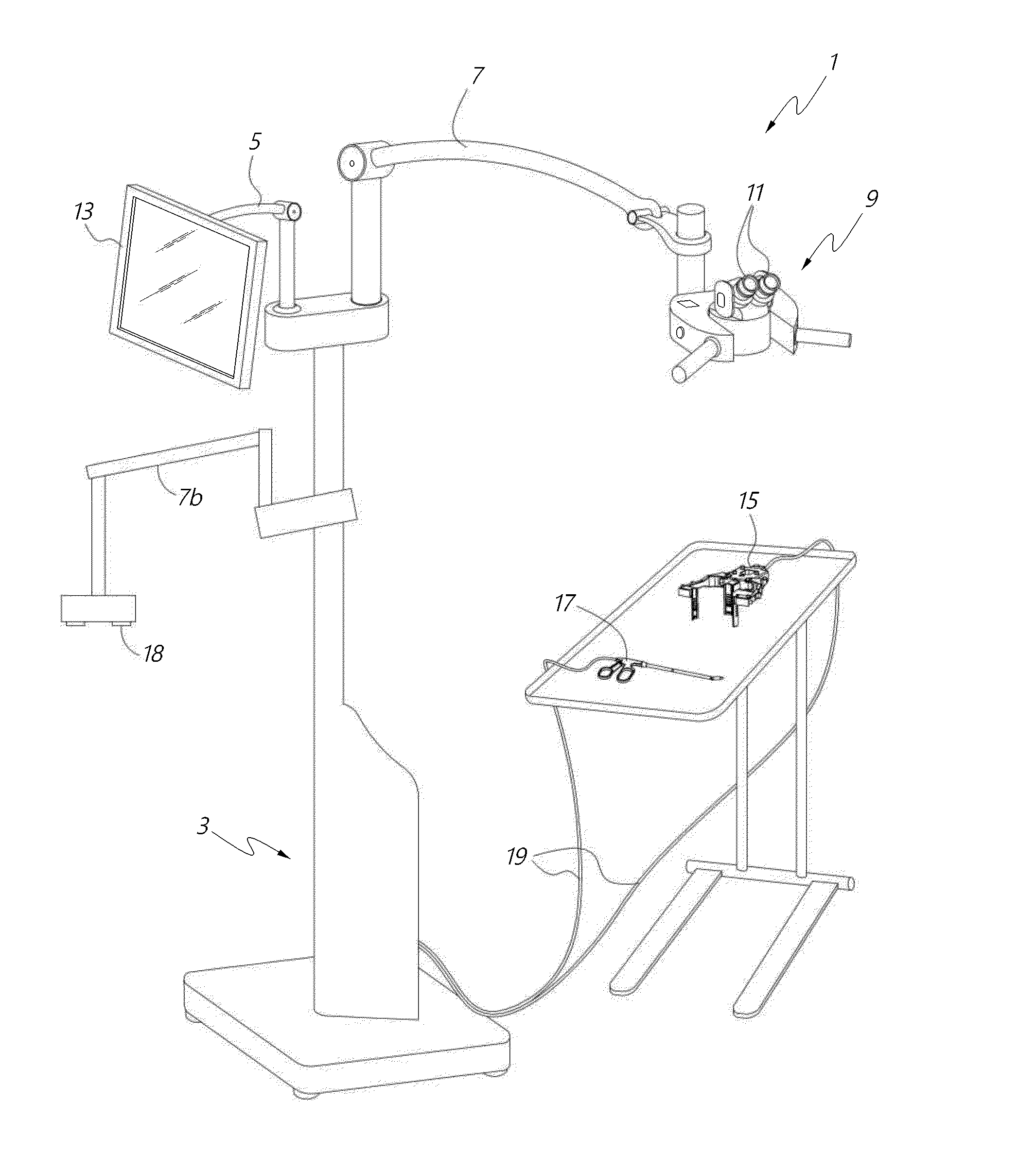
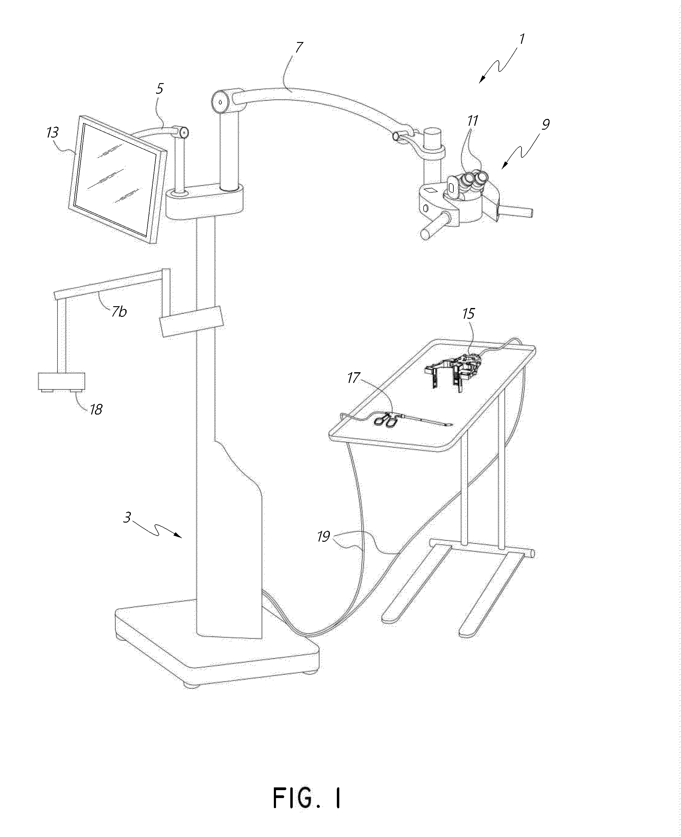
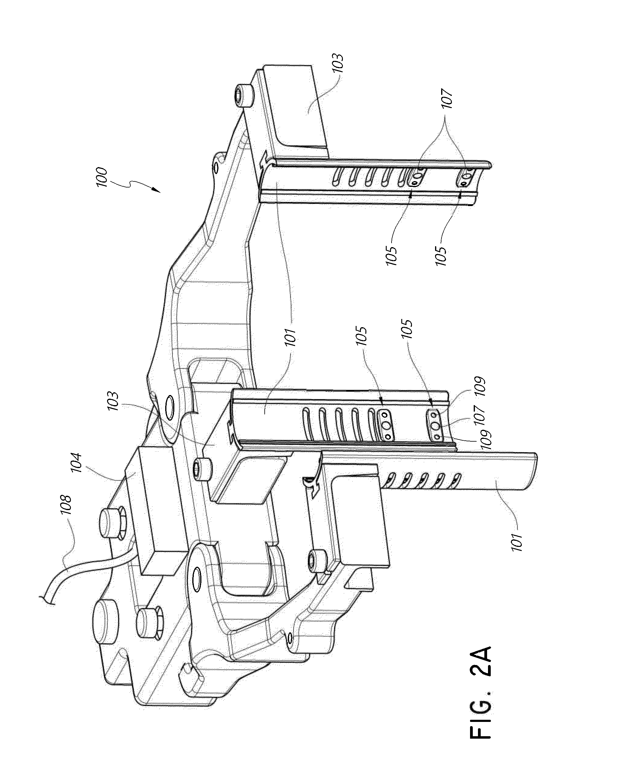
[0174]With continued reference to FIGS. 7A and 7B, in some embodiments, the movement control system 10100 can be attached to an attachment structure, such as binocular display unit 9, and support one or more imagers 18. As shown in the illustrated embodiment, the movement control system 10100 can be oriented generally underneath the binocular display unit 9 and in some embodiments can be sized such that the movement control system 10100 does not extend significantly beyond the outer housing of the binocular display unit 9. This can advantageously provide a smaller form factor thereby reducing the likelihood that the movement control system 10100 will interfere with the medical professionals and assistants during a medical procedure. In other embodiments, the attachment structure can be other components of the surgical visualization system 1 such as, but not limited to, a dedicated articulating arm or a display arm. In some embodiments, the movement control system 1...

example 1

[0221]

SurfRadiusThicknessGlassDiameterMirror (1st turning)STOPInfinity3015Mirror (2nd turning)168.176N-FK5252−2823SF6253Infinity106.4825(mirror)4337.34N-BK7255−186.752SF2256−557.45.816257−43.143N-BK7258−1009.621259−33.962N-BAF10251032.514.5N-SF6HT2511189.23187.89724.3(mirror)12Infinity0.01BK7130.2Display130.2(Diagonal)

[0222]The input field of view, 2ω, is 6 degrees, but could be 3 degrees or as much as 10 degrees.

[0223]Various embodiments for the optical path of the assistant surgeon display take the form of the following:

example 2

[0224]

SurfRadiusThicknessGlassDiameterMirror (1st turning)STOInfinity3517.52−28.452.6N-SF6283−372304−6805.6N-BK7305−43.295030638.48N-SSK830739.6842.71828(mirror)8−30.74F2289−43.2948.9330(mirror)Display27.85(Diagonal)

[0225]The input field of view, 2ω, (for example, of the electronic display e.g., LCD or LED display) is 6 degrees, but could be 3 degrees or as much as 10 degrees.

[0226]In the above embodiments, the relation between the input field angle, 2ω, and angle theta, the marginal field angle, on the display, the source, is shown below:


PUM


Abstract

A medical apparatus is described for providing visualization of a surgical site. The medical apparatus includes an electronic display disposed within a display housing, the electronic display configured to produce a two-dimensional image. The medical apparatus includes a display optical system disposed within the display housing, the display optical system comprising a plurality of lens elements disposed along an optical path. The display optical system is configured to receive the two-dimensional image from the electronic display, produce a beam with a cross-section that remains substantially constant along the optical path, and produce a collimated beam exiting the opening in the display housing. The medical apparatus can also include an auxiliary video camera configured to provide an oblique view of a patient on the electronic display without requiring a surgeon to adjust their viewing angle through oculars viewing the electronic display.

Description

CROSS-REFERENCE TO RELATED APPLICATIONS[0001]This application claims the benefit of priority to U.S. Prov. App. No. 61 / 920,451, entitled “SURGICAL VISUALIZATION SYSTEMS”, filed Dec. 23, 2013; to U.S. Prov. App. No. 61 / 921,051, entitled “SURGICAL VISUALIZATION SYSTEMS”, filed Dec. 26, 2013; to U.S. Prov. App. No. 61 / 921,389, entitled “SURGICAL VISUALIZATION SYSTEMS”, filed Dec. 27, 2013; to U.S. Prov. App. No. 61 / 922,068, entitled “SURGICAL VISUALIZATION SYSTEMS”, filed Dec. 30, 2013; to U.S. Prov. App. No. 61 / 923,188, entitled “SURGICAL VISUALIZATION SYSTEMS”, filed Jan. 2, 2014; and to U.S. Prov. App. No. 62 / 088,470, entitled “SURGICAL VISUALIZATION SYSTEMS AND DISPLAYS”, filed Dec. 5, 2014. Each of the applications cited in this paragraph is incorporated by reference herein in its entirety.BACKGROUND[0002]1. Field[0003]Embodiments of the present disclosure relate to visualization systems and displays for use during surgery.[0004]2. Description of Related Art[0005]Some surgical ope...

Claims


Application Information

Patent Timeline
IPC IPC(8): A61B19/00G06T7/00A61B6/03A61B8/13A61B1/05A61B5/055
CPCA61B19/5225A61B1/05A61B5/055A61B6/032A61B8/13G06T2207/20221G06T7/0024G06T2207/10064G06T2207/10068G06T2207/10132G06T2207/10081A61B19/5223G02B21/0012G02B21/16G02B21/22A61B17/0206A61B2017/00535A61B2090/306A61B90/20A61B90/37A61B2090/364A61B90/361A61B17/1611A61B2090/371A61B2034/2048A61B2034/2051A61B2034/2055G06T7/30
Inventor TESAR, JOHN
Owner CAMPLEX
Why Eureka
Try Eureka