Spatially coded structured light generator

a generator and structured light technology, applied in the field of spatial coded structured light generators, can solve the problems of not reaching an intensity, limited first approach, and complex optical sub-systems

Active Publication Date: 2015-10-22
IEE INT ELECTRONICS & ENG SA
View PDF15 Cites 44 Cited by
  • Summary
  • Abstract
  • Description
  • Claims
  • Application Information

AI Technical Summary

Benefits of technology

[0013]The system described herein shall overcome these limitations and fulfil b

Problems solved by technology

This strategy thus requires the acquisition of a reference frame, since the scene is not uniform in spectral reflectivity.
Furthermore the optical sub-system becomes quite complex.
The first approach is limited, with c

Method used


Image

  • Spatially coded structured light generator
  • Spatially coded structured light generator
  • Spatially coded structured light generator

Examples


Embodiment Construction

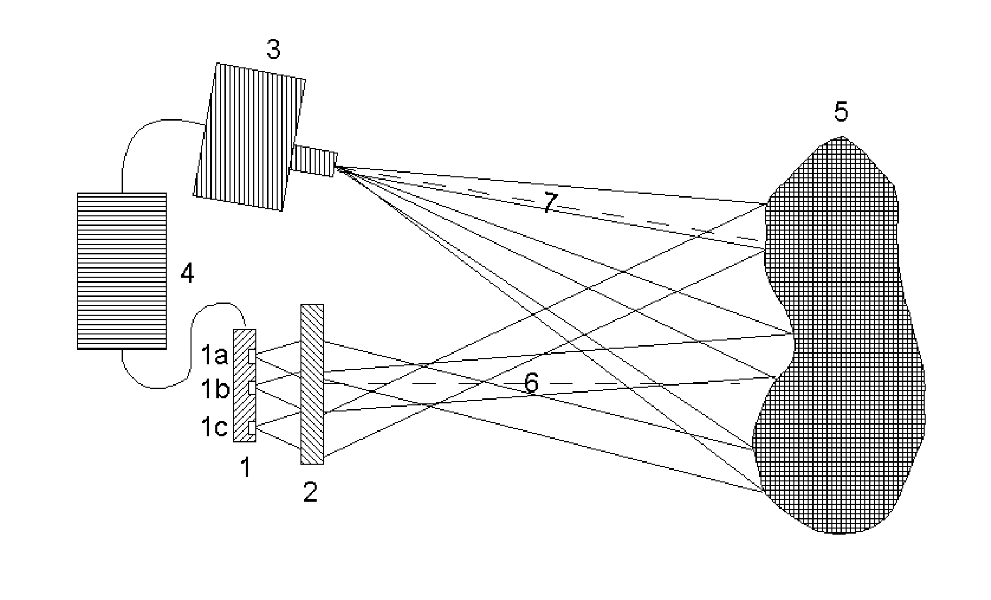
[0019]A configuration for structured light triangulation is shown schematically in FIG. 1. The reference numbers indicate:[0020]1: an array of monolithically integrated surface emitting laser diodes[0021]1a-1c: individual laser diodes[0022]2: projection optics[0023]3: camera[0024]4: power, control and processing unit[0025]5: object in the scene[0026]6: illumination optical axis[0027]7: camera optical axis.

[0028]The unit 4 powers the array of laser diodes. The projection optics 2 projects the light emitted by the individual laser diodes, forming the spatially coded structured light pattern in the scene. The unit 4 starts the acquisition of a frame, and retrieves the data from the camera 3, once a complete frame has been captured. The unit 4 processes these data, and constructs the 3D map of the scene.

[0029]The array of monolithically integrated surface emitting laser diodes is manufactured according to the standard processes for such lasers, except that the masks used to process the ...


PUM


Abstract

A spatially coded structured light is generated by an array of laser diodes (1) in order to perform structured light triangulation. The laser diodes (1a-c) are VCSEL, where the light is emitted in the direction perpendicular to the semiconductor wafer surface. Plural such laser diodes (1a-c) are integrated monolithically to form an array (1). The position of the individual laser diodes in the array is coded spatially to form a non-regular unique pattern. The light output by the lasers is projected by a refractive or diffractive optical system (2) into the space to be monitored to form the structured light pattern. An object (5) to be investigated may be illuminated by the VCSEL array (1) and a camera (3) captures the frames. A processing unit (4) controls the power of VCSEL (1a-c) and processes the data from the camera (3).

Description

TECHNICAL FIELD[0001]The present invention generally relates to the field of 3D mapping by structured light triangulation. More specifically, the invention relates to a spatially coded structured light generator based on an array of monolithically integrated surface emitting laser diodes.BACKGROUND ART[0002]3D mapping of a scene by structured light triangulation comprises illuminating the scene with a light pattern and observing the illuminated scene with a camera whose optical axis is offset from the illumination source. If a given ray from the illumination intersects a reflective object, an image of this ray will by formed on the camera. The location of the image of this ray together with knowledge about the exact geometry of illumination-imaging setup allows the determination of the relative position of the intersection between the light ray and the object. This supposes that one knows which ray of the structured light pattern intersected the object. Finding the ray of the patter...

Claims


Application Information

Patent Timeline
IPC IPC(8): G01S17/89G01S7/481G01S17/48
CPCG01S17/89G01S7/4815G01S17/48H01S5/005H01S5/18394H01S5/423G01B11/2513
Inventor HERSCHBACH, NORBERTKAISER, JEAN-LUC
Owner IEE INT ELECTRONICS & ENG SA
Why Eureka
Try Eureka