Thermoelectric conversion element, use of the same, and method of manufacturing the same
a technology of thermoelectric conversion element and monocrystalline ferrite, which is applied in the manufacture/treatment of thermoelectric devices, thermoelectric device details, and thermoelectric devices. it can solve the problems of conventional spin current thermoelectric conversion element using monocrystalline ferrite and suffer from random oriented grain boundaries of ferri
- Summary
- Abstract
- Description
- Claims
- Application Information
AI Technical Summary
Benefits of technology
Problems solved by technology
Method used
Image

Examples
first embodiment
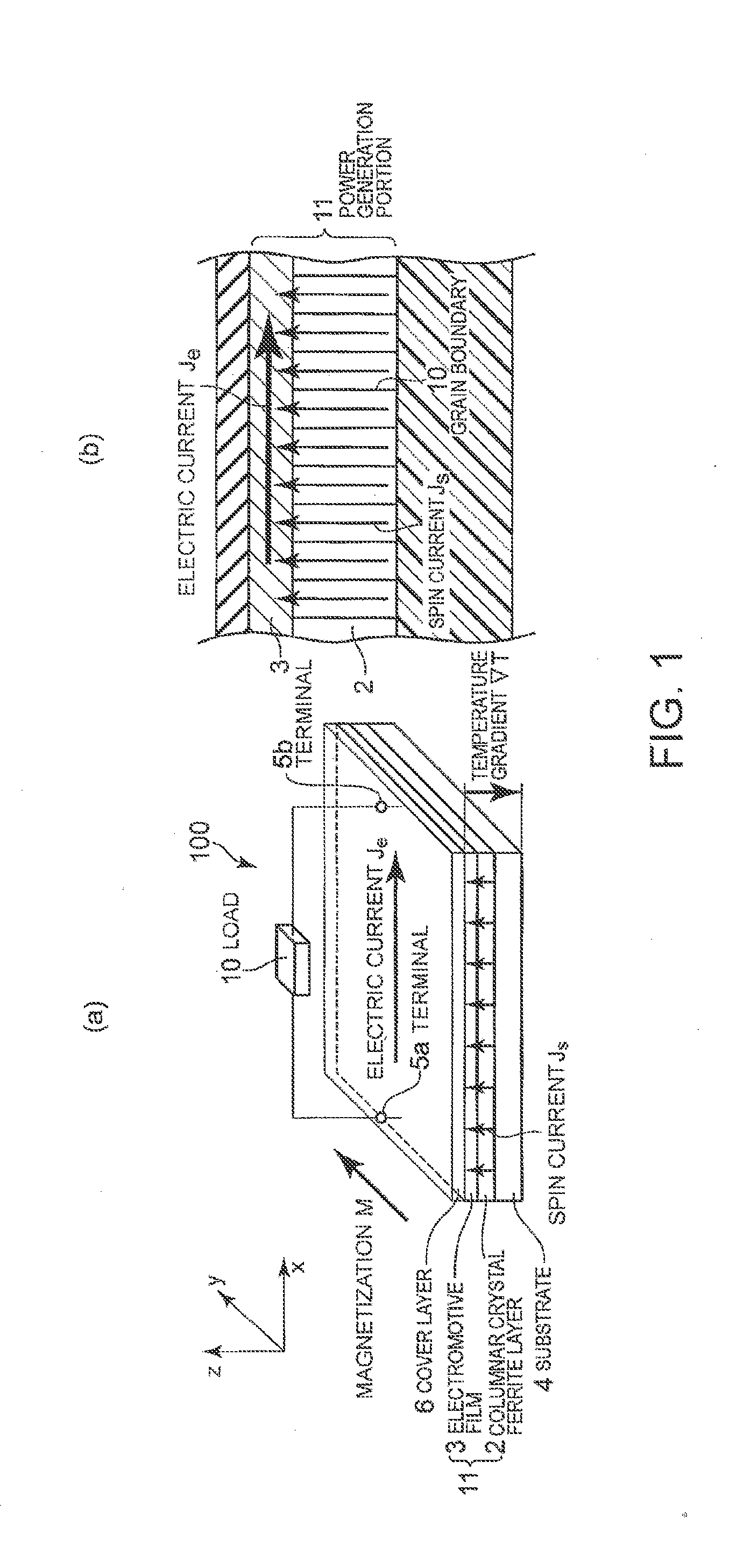
[0050]A first embodiment of the present invention describes a flexible thermoelectric conversion element.
[0051]The inventors have found that a flexible thermoelectric conversion element demonstrating performance that is equivalent to the performance of a thermoelectric conversion element using a monocrystalline ferrite can be formed by use of a columnar crystal ferrite material.
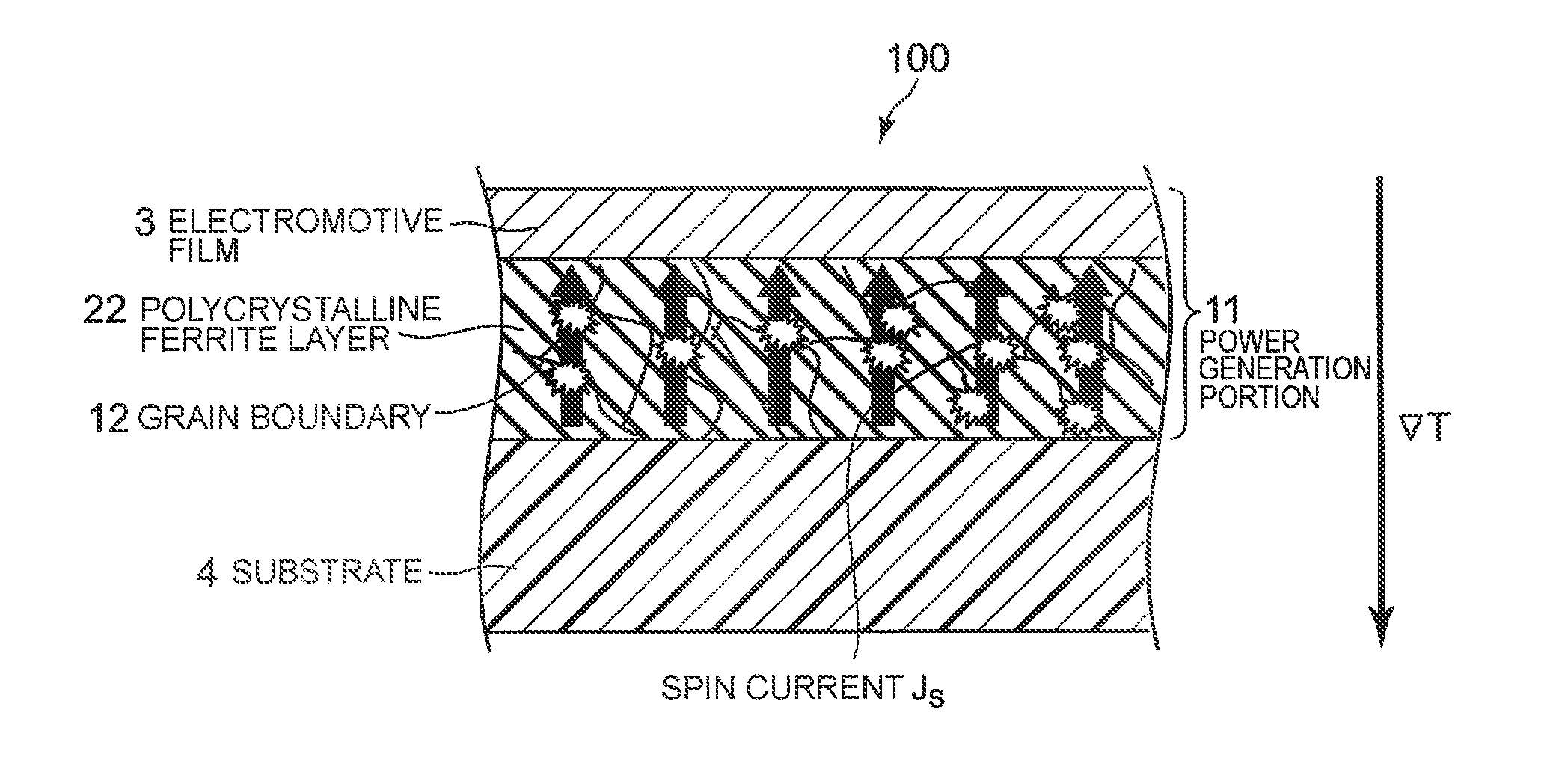
[0052]Here, columnar crystal refers to a crystalline structure in which each crystal grain of a film comprises a columnar shape that is elongated in the perpendicular-plane direction. With such a columnar crystal film, scattering factors that inhibit thermal spin current driving in the perpendicular-plane direction are reduced as compared to a polycrystalline film having randomly oriented grain boundaries. Therefore, such a columnar crystal film has been found to be preferable for a magnetic film used for a thermoelectric conversion element using the spin Seebeck effect.
[0053]Furthermore, large grain boundari...
second embodiment
[0104]A multilayer thermoelectric conversion element will be described in a second embodiment of the present invention.
[0105]FIG. 6(a) is a perspective view showing a multilayer thermoelectric conversion element using a columnar crystal ferrite according to the second embodiment of the present invention, and FIG. 6(b) is a partial enlarged cross-sectional view of FIG. 6(a).
[0106]In the first embodiment, there is provided only one layer of the power generation portion 11 including the columnar crystal ferrite layer 2 and the electromotive film 3. If the film thickness of the columnar crystal ferrite layer 2 and the electromotive film 3 is small, it is difficult to hold a large temperature difference. Therefore, a high electric power cannot be obtained.
[0107]As shown in FIGS. 6(a) and 6(b), in the second embodiment of the present invention, a plurality of layers of the power generation portions 11 are stacked to form a thermoelectric conversion element that can output a higher electri...
third embodiment
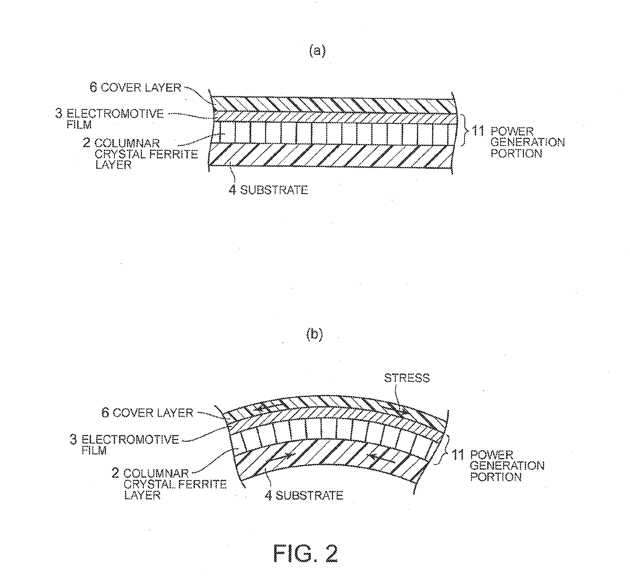
[0112]A thermoelectric conversion coating to a heat source comprising a curved surface or a surface with irregularities will be described in a third embodiment of the present invention.
[0113]FIG. 8 is a cross-sectional view showing a thermoelectric conversion element according to the third embodiment of the present invention. FIG. 8 shows thermoelectric coating using a columnar crystal ferrite. FIG. 9 is a cross-sectional view explanatory of an operative advantage of thermoelectric coating using a columnar crystal ferrite illustrated in FIG. 8.
[0114]The third embodiment of the present invention illustrates thermoelectric coating to a heat source having a curved surface or a surface with irregularities. For a heat source having a curved surface or a surface with irregularities, a flexible thermoelectric conversion element as shown in the first embodiment may be arranged along the surface of the heat source. Nevertheless, the same effects can also readily be attained by a method of di...
PUM
| Property | Measurement | Unit |
|---|---|---|
| thickness | aaaaa | aaaaa |
| thickness | aaaaa | aaaaa |
| thickness | aaaaa | aaaaa |
Abstract
Description
Claims
Application Information
 - R&D
- Intellectual Property
- Life Sciences
- Materials
- Tech Scout
- Unparalleled Data Quality
- Higher Quality Content
- 60% Fewer Hallucinations
Browse by: Latest US Patents, China's latest patents, Technical Efficacy Thesaurus, Application Domain, Technology Topic, Popular Technical Reports.
© 2025 PatSnap. All rights reserved.Legal|Privacy policy|Modern Slavery Act Transparency Statement|Sitemap|About US| Contact US: help@patsnap.com