Layered manufacturing of free-form multi-material micro-components

Active Publication Date: 2015-10-29
DIGITAL METAL
View PDF0 Cites 45 Cited by
  • Summary
  • Abstract
  • Description
  • Claims
  • Application Information

AI Technical Summary

Benefits of technology

[0009]In view of the above-mentioned and other drawbacks of the prior art, a general object of the present invention is to provide manufacturing of 3D-objects containing several materials with additive layered manufacturing. The invention enables efficient production of objects consisting of a powd

Problems solved by technology

Other methods that can build objects by dispensing at each point or use a single laser or electron beam spot for selective solidification are inherently slower since they can only build at one point at a time.
The latter method is very fast but it is limited to coarser powders with approximately 10-20 μm particle size that can be spread homogenously in the dry state

Method used


Image

  • Layered manufacturing of free-form multi-material micro-components
  • Layered manufacturing of free-form multi-material micro-components
  • Layered manufacturing of free-form multi-material micro-components

Examples


example 1

[0033]In a simple model experiment a doctor blade casting station was used instead of slot die for manual application of layers. On a plate of sintered alumina a metallic pattern was screen printed. The pattern consisted of straight conductor lines in different dimensions finished by a contact point, FIG. 3. Printing was done with a silver paste to have good electrical conduction.

[0034]The plate with the conductor was placed in the casting station. An alumina suspension (40 vol % AKP 30, Sumitomo Chemicals), in water with a dispersing agent (0.35% Dolapix PC21) was cast with a doctor blade with 80 μm gap. This casting created a film with fine alumina powder on the plate.

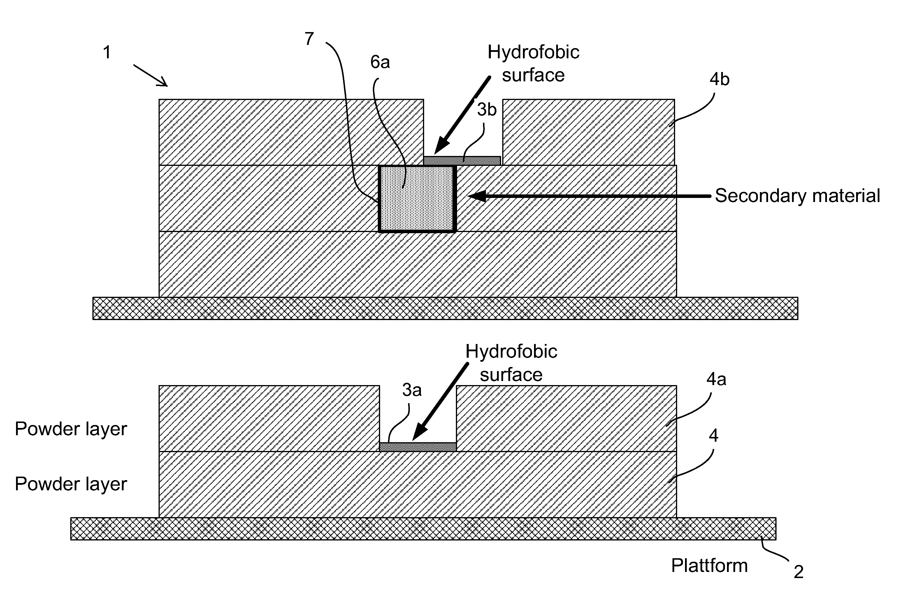
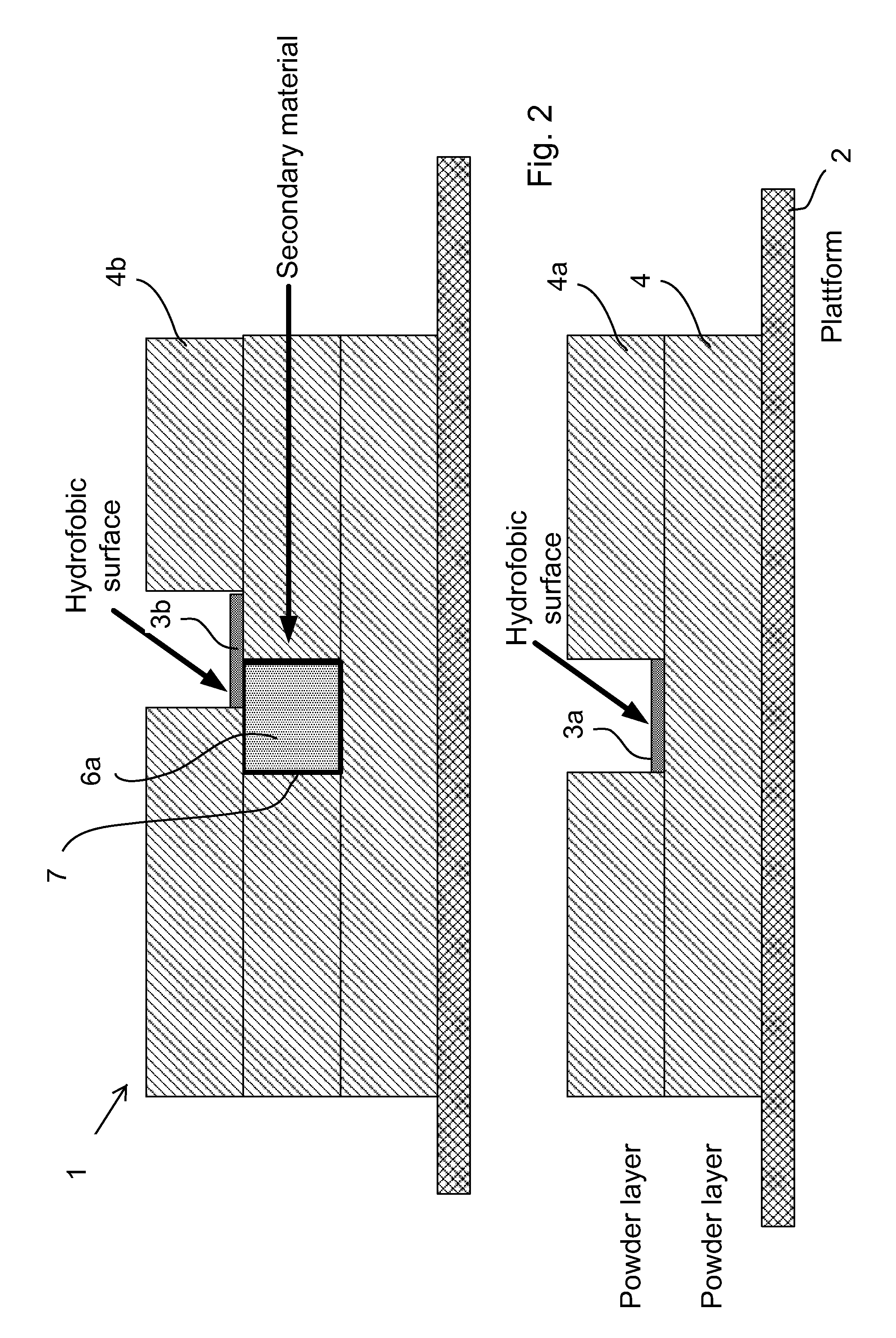
[0035]Holes for vias were created by dispensing of a hydrophobic liquid. The hydrophobic liquid was a fluorocarbon based liquid. On areas where the hydrophobic liquid was applied the alumina water-based suspension did not wet and thus it avoided those areas. Holes are created that penetrate the dry alumina powder lay...

example 2

[0038]A machine for layer manufacturing was built. It consists of a table with linear actuators (NSK and HIWIN) that can move a stage in x-y-z directions. The movable stage is controlled with a PLC controller (Beijer).

[0039]The movable stage is fitted with a slot die (Premier Dies) fed by a ceramic suspension under pressure with a precision pump (such as a precision gear pump). The ceramic suspension is similar to example 1 but the solids concentration was adjusted to a viscosity suitable for the slot die.

[0040]Inkjet heads (HP) with a drive electronic (Megatech Electronic) was fixed to the stage to be able to print both a temporary latex binder and a hydrophobic liquid.

[0041]Dispensers were also fitted to the movable stage and filled with conductive paste.

[0042]A computer was programmed to control the slot die through the PLC and to transfer printing information to drive printing electronic for each layer. The movable stage was then raised before deposition of the next layer.

[0043]...


PUM

PropertyMeasurementUnit
Lengthaaaaaaaaaa
Lengthaaaaaaaaaa
Dielectric polarization enthalpyaaaaaaaaaa

Abstract

The present invention relates to layer manufacturing, more particularly to a method for additive layer manufacturing of objects comprised of more than one material with free-form capability for all included materials. The invention can for example be used for producing packaging for Microsystems where the ceramic acts as an insulator and the secondary material is used to produce electrical or optical 3D conductor lines or electrical or optical 3D vias. The fine powder used in this method enables it to be used for building components with small feature size and demand for high precision. Other intended uses for this method is to build small mechanical precision parts or grinding tools, dental objects or medical implants.

Description

FIELD OF THE INVENTION[0001]The present invention relates to layer manufacturing, more particularly to a method for additive layer manufacturing of objects comprised of more than one material with free-form capability for all included materials.[0002]The invention deals with a method to fabricate objects by starting with a virtual 3D model (CAD-model) and using this information to add material in a controlled manner to shape the object. These types of methods are commonly referred to by a number of terms for example rapid prototyping, free-form fabrication, layer manufacturing and additive manufacturing. 3D-printing is one method that belongs to this group. Since objects with very complex shapes can be described by a set of planar layers this method makes it possible to fabricate any desired shape within the precision of the actual implementation of these layered manufacturing methods.BACKGROUND ART[0003]3D-printing is a method where a powder layer is distributed on a surface. An in...

Claims


Application Information

Patent Timeline
IPC IPC(8): B22F3/00B28B1/00B22F5/00
CPCB22F3/008B22F5/00B33Y40/00B22F2005/001B33Y10/00B28B1/001C22C5/06C22C29/12B22F3/22B22F5/10B22F2999/00A61C13/0013A61C13/0018H05K3/4667H05K1/0272H05K1/0274H05K1/0306H05K3/1208H05K2201/09981H05K2203/0126H05K2203/013H05K2203/122B29C64/165B33Y80/00B22F10/10Y02P10/25B22F12/33B33Y40/20B28B1/00B22F10/14B33Y70/00C04B35/622B33Y70/10
Inventor KLINT, THORBJORNCARLSTROM, ELISJOHANDER, PERSTIEMSTEDT, JOHANNA
Owner DIGITAL METAL
Why Eureka
Try Eureka