
Multi-stage radial flow turbine

a radial flow turbine and multi-stage technology, applied in liquid fuel engines, renewable energy generation, greenhouse gas reduction, etc., can solve the problems of limited conventional axial flow designs, achieve significant performance improvement, reduce the energy content of feed streams, and less efficient effects

Inactive Publication Date: 2015-11-12
FRENCH JOHN
View PDF5 Cites 6 Cited by
  • Summary
  • Abstract
  • Description
  • Claims
  • Application Information

AI Technical Summary

Benefits of technology

The present invention is a multi-stage radial turbine that can capture energy from slow-moving fluids such as wind and water. It can be used in a variety of devices, including those that run on land or water. The design is unique, as it uses a radial orientation to improve efficiency, resulting in better performance compared to previous designs. Additionally, combining a radial compressor, burner, and energy capturing turbine creates an internal combustion engine that operates efficiently at slower flow speeds. Overall, the present invention provides improved performance and efficiency at low fluid speeds.

Problems solved by technology

The conventional axial flow designs are limited by the amount of energy contained in the fluid stream.

Method used


Image

  • Multi-stage radial flow turbine
  • Multi-stage radial flow turbine
  • Multi-stage radial flow turbine

Examples


Embodiment Construction

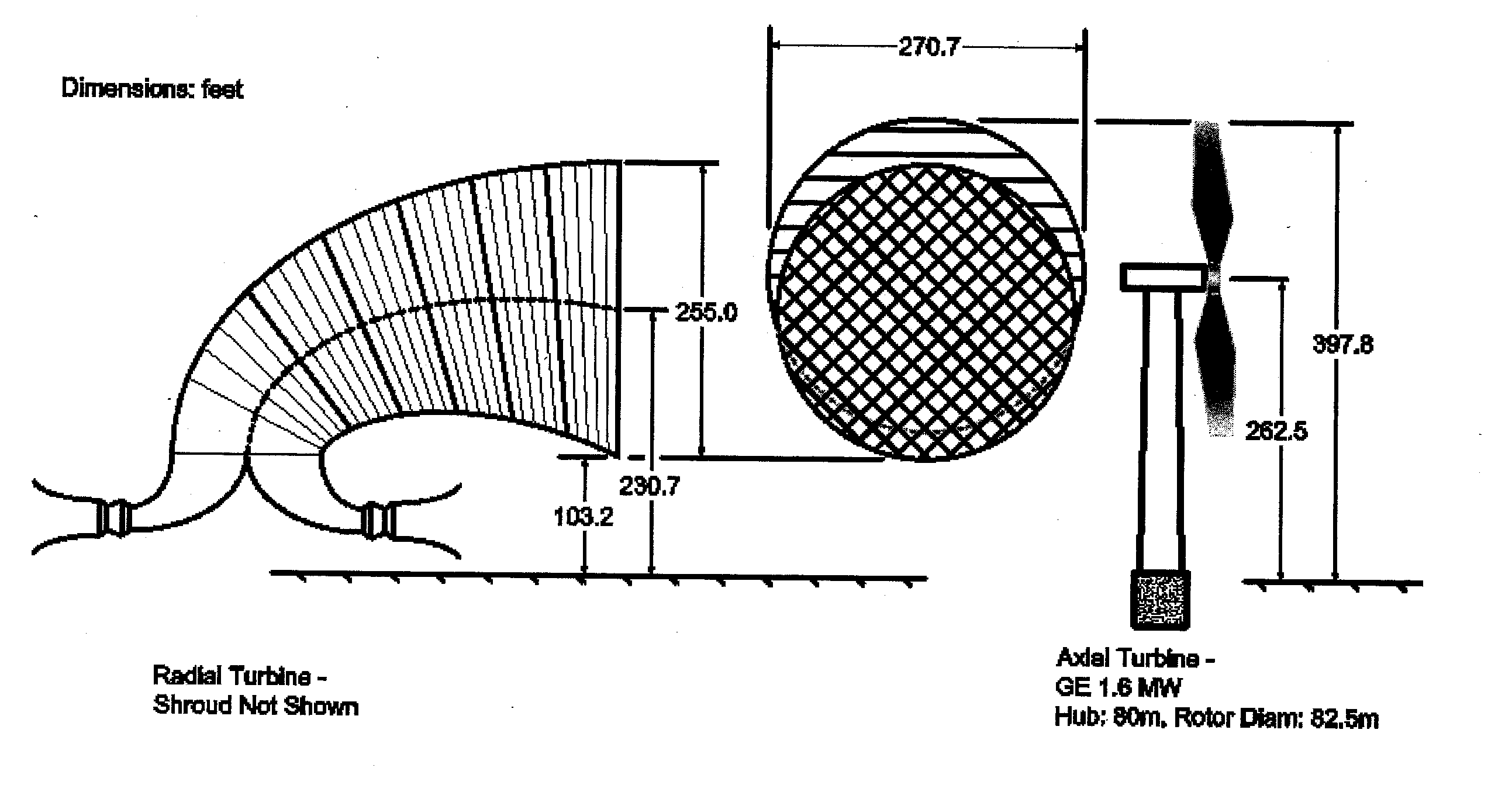
[0048]Referring now in greater detail to the drawings, wherein these showings are for the purpose of illustrating various embodiments of the invention only, and not for the purpose of limiting the invention, the present invention is directed to a multi-stage radial turbine for usage in energy capture from fluid streams with low to moderate velocity. One non-limiting advantage of the radial design is that it can operate efficiently in flow conditions that are much slower and / or have rotational speeds that are greatly reduced than the necessary minimum speeds for axial designs. Additional discussion and quantification of expected performance gains by controlling secondary flows are set forth in more detail below.

Power from Wind

[0049]In one non-limiting aspect of the present invention, the invention is directed to a radial design having improved performance for producing electrical power from wind-driven devices. Several of the design aspects of the wind-driven turbine have a direct co...


PUM


Abstract

Various multi-stage radial turbine configurations that provide highly efficient momentum transfer between a fluid and the mechanical interface in both power producing and power consuming undertakings.

Description

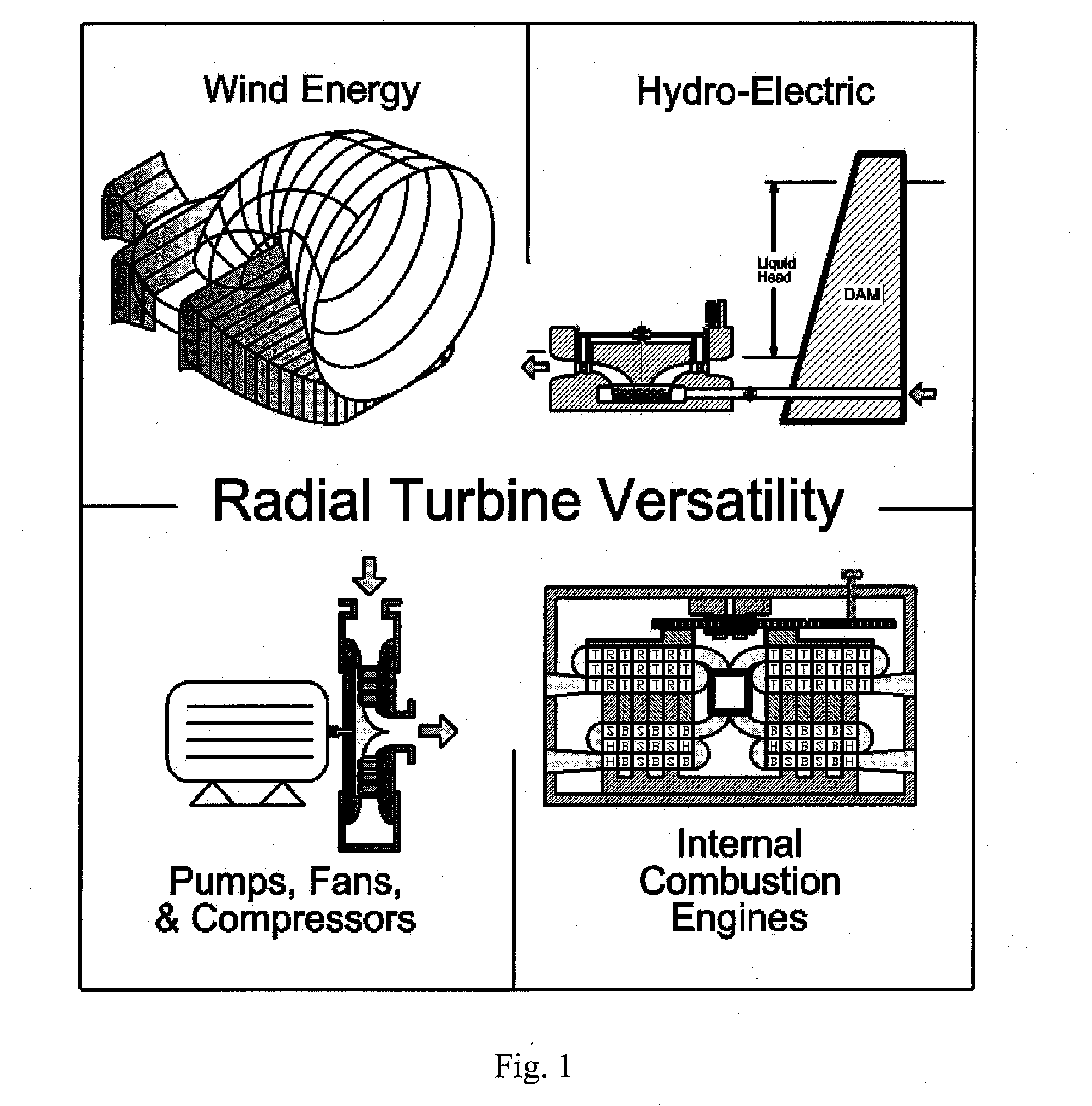
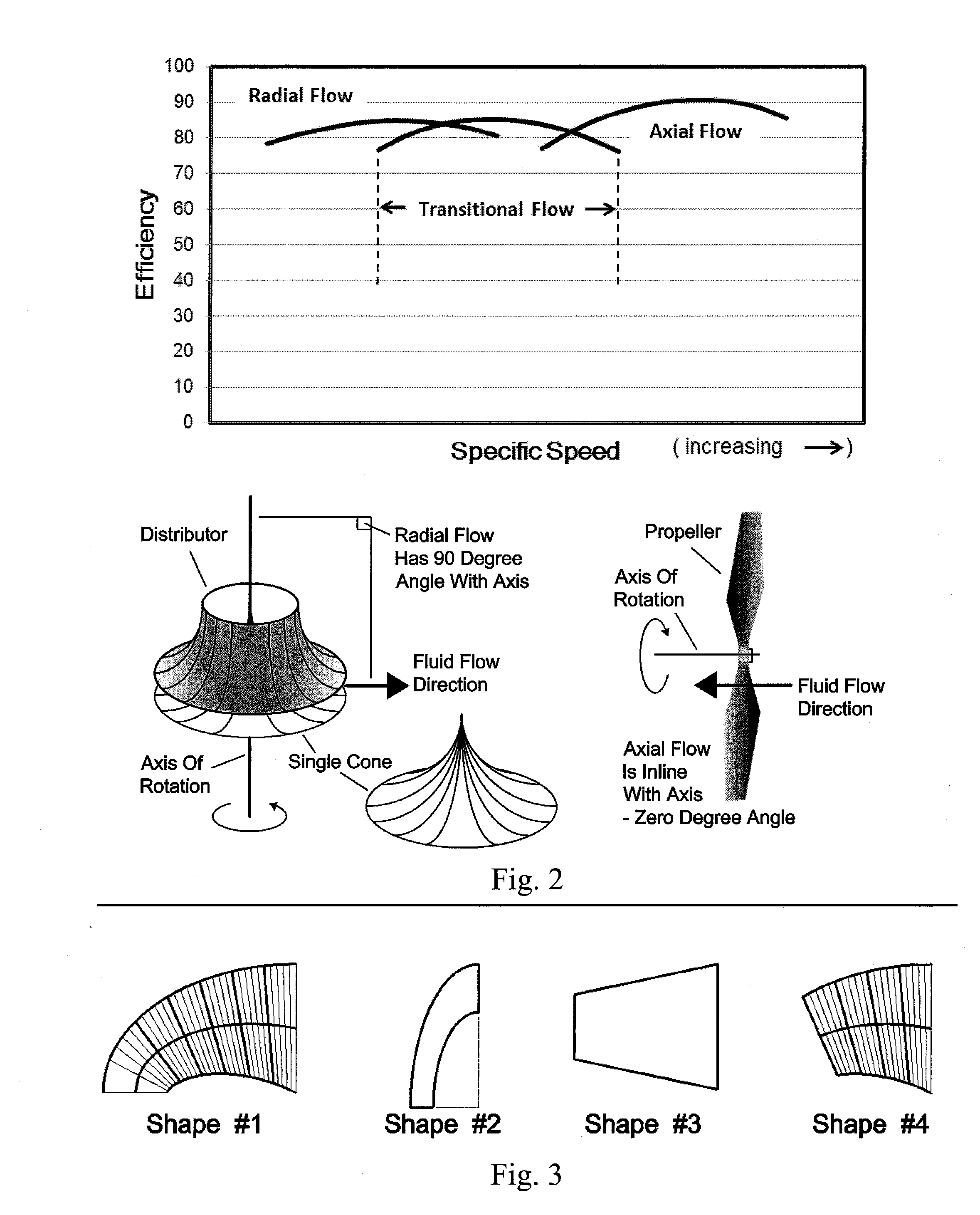
[0001]The present invention is a continuation-in-part of U.S. patent application Ser. No. 14 / 209,019 filed Mar. 13, 2014, which in turn claims priority on U.S. Provisional Patent Application Ser. No. 61 / 782,044 filed Mar. 14, 2013, which are all incorporated herein by reference.[0002]The present invention is directed to a multi-stage radial turbine for usage in energy capture from fluid streams with low to moderate specific speed. The turbine can also be driven and used as a very efficient liquid pump and gaseous phase fan or compressor. Additionally, combining compression, a burner, and energy capture creates a new type of internal combustion engine. FIG. 1 introduces and illustrates most simply some of the wide range of configurations that can utilize this new type of turbine.BACKGROUND OF THE INVENTION[0003]Various radial designs for a turbine have been utilized since the dawn of the industrial revolution and their characteristic flow is found in numerous patents. FIG. 2 provides...

Claims


Application Information

Patent Timeline
Patent Type & Authority Applications(United States)
IPC IPC(8): F01D25/24F01D5/04F01D5/06F01D17/10F01D11/00F01D15/10F01D15/08F01D1/06F01D9/04
CPCF01D25/24F01D1/06F01D5/04F01D5/06F01D17/105F01D11/005F01D15/10F01D15/08F01D9/041F03B3/00F03B13/08F03D3/005F03D3/02F03D3/0427F03D9/00F05B2210/16F05B2240/13F05B2240/93F05B2240/941F03D13/20Y02E10/20Y02E10/72Y02E10/727Y02E10/74Y02T50/60F03D1/04F03D9/25
Inventor FRENCH, JOHN
Owner FRENCH JOHN
Learn More