Oscillating foil propulsion system and method for controlling a motion of an oscillating movable foil

Inactive Publication Date: 2015-11-19
ABB OY
View PDF13 Cites 2 Cited by
  • Summary
  • Abstract
  • Description
  • Claims
  • Application Information

AI Technical Summary

Benefits of technology

[0029]The present invention especially improves the propulsor efficiency of the foil over prior art. The efficiency improvement leads to reduced fuel consumption of the vessel and therefore to a longer maximum range as well as reduced emissions. Another advantage is the possibility to reduce the volume of the fuel tanks which increases the space for valuable payload on board. A combination of the aforementioned advantages, i.e. reduction of fuel consumption and reduction of fuel tank volume, is also possible.
[0030]Additionally, model tests of a propulsion system according to an embodiment of the invention have indicated that a propulsor efficiency of 50%-70% or greater can be achieved, which is in the range of or significantly greater than the efficiency of a conventional propeller. The wetted propulsion surface of the at least one foil can be larger than the area of a conventional propeller which reduces the area load. The propulsion system is especially suited for so called ho

Problems solved by technology

Further optimization of conventional screw propellers has become more difficult and therefore new propulsive devices are needed, which, for example, produce thrust by a movement of an oscillating fin, which mimics the manner in which dolphins or whales swim.
Therefore, the apparatus according to document US 2011/0255971 A1 allows adjustment of the frequenc

Method used


Image

  • Oscillating foil propulsion system and method for controlling a motion of an oscillating movable foil
  • Oscillating foil propulsion system and method for controlling a motion of an oscillating movable foil
  • Oscillating foil propulsion system and method for controlling a motion of an oscillating movable foil

Examples


Example

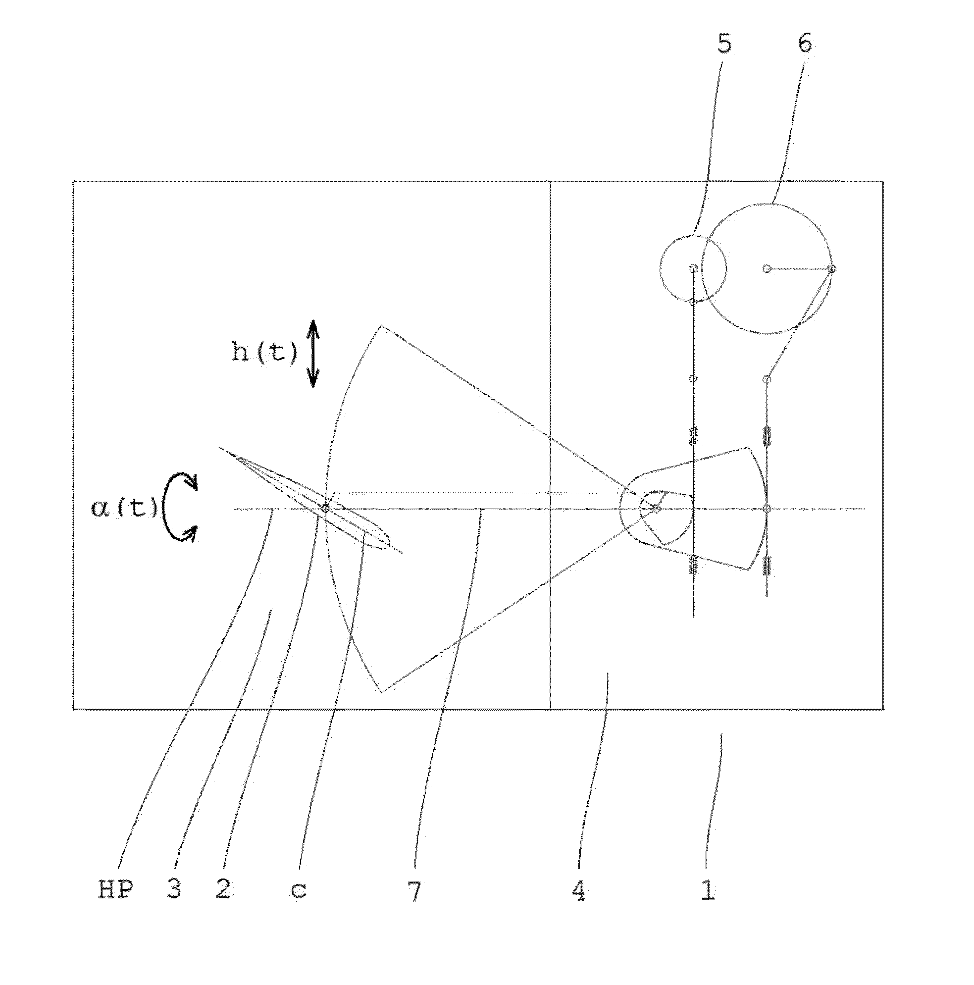
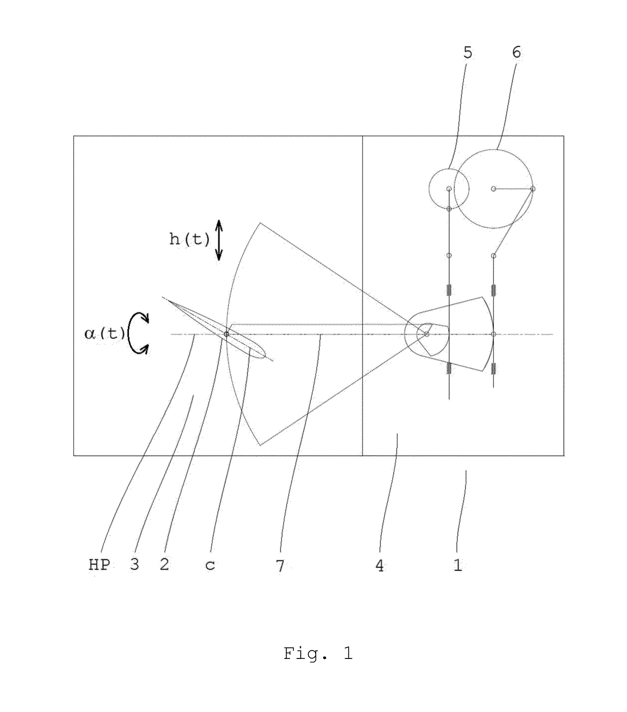
[0043]In FIG. 1 a schematic view of a propulsion system 1 according to a first embodiment of the invention is illustrated. The propulsion system 1 includes a movable foil 2 which is arranged in a fluid 3 outside a body 4. The system 1 further includes a pitch mechanism 5 for adjusting a pitch angle α(t) between the chord line c of the foil 2 and a horizontal plane HP, a frequency f1(t) of the pitch motion, and an amplitude A1(t) of the pitch motion of the movable foil 2. The system 1 also includes a heave mechanism 6 for adjusting a heave h(t) of the movable foil in vertical direction, a frequency f2(t) of the heave motion, and an amplitude A2(t) of the heave motion of the movable foil 2. The pitch and heave mechanisms 5, 6 are arranged inside the body 4. A connector 7 is extending from outside the body 4 to inside the body 4 and is connected to and adapted to interact with the pitch mechanism 5, the heave mechanism 6 and the movable foil 2. The movable foil may have a symmetrical o...

Example

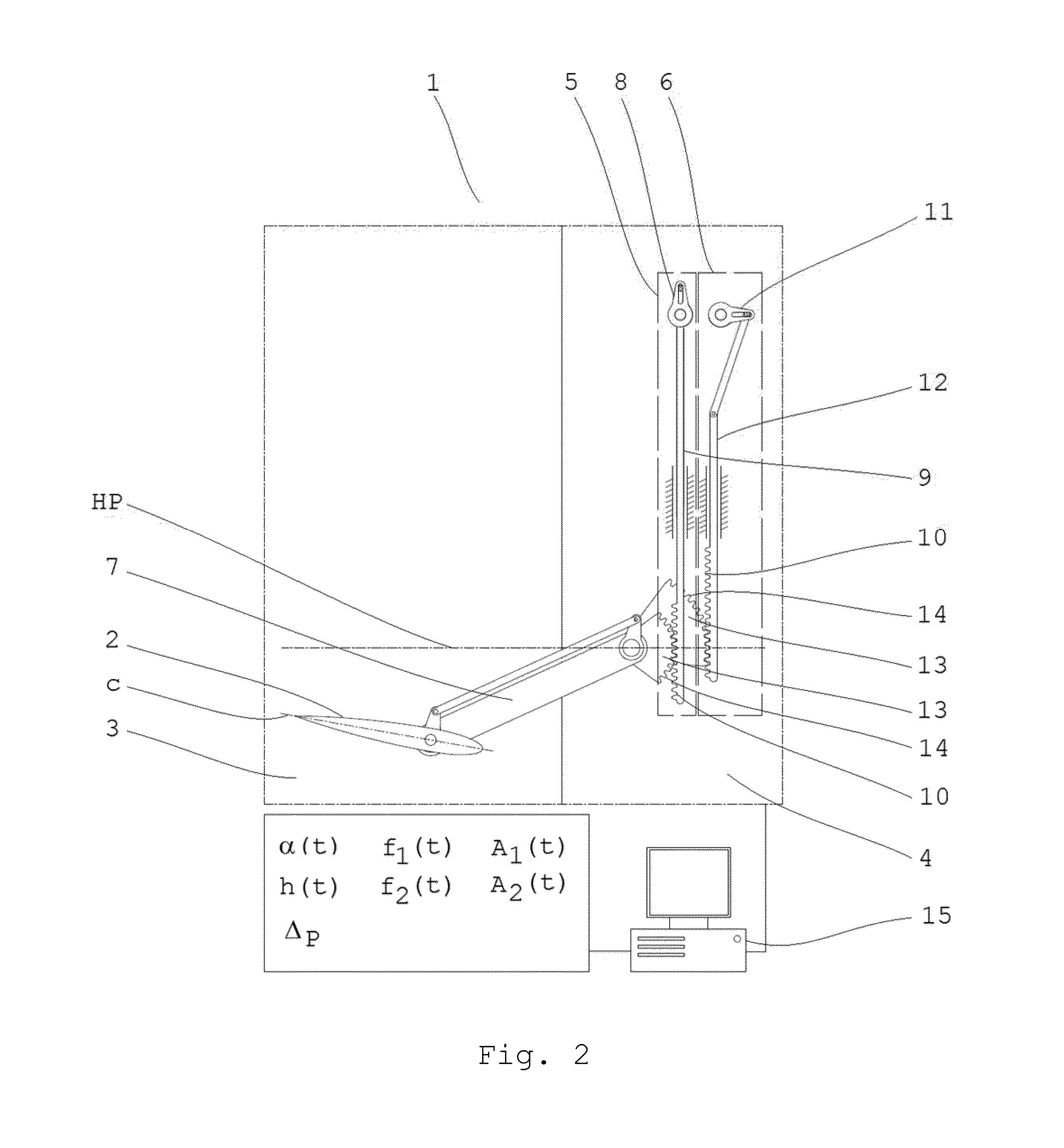
[0044]In FIG. 2 a schematic view of a propulsion system 1 according to a second embodiment of the invention is illustrated. The propulsion system 1 includes a movable foil 2, which is arranged in a fluid 3 outside a body 4. The system 1 further includes a pitch mechanism 5 for adjusting a pitch angle α(t), a frequency f1(t) of the pitch motion, and an amplitude A1(t) of the pitch motion of the movable foil 2 and a heave mechanism 6 for adjusting a heave h(t), a frequency f2(t) of the heave motion, and an amplitude A2(t) of the heave motion of the movable foil 2. The pitch and heave mechanisms 5, 6 are arranged inside the body 4. The pitch mechanism 5 includes a first crank mechanism 8, a movable pitch slider 9 which is connected to the first crank mechanism 8 on one side, and rack pinions 10 which are connected to, arranged on, or an integral part of the pitch slider 9. The heave mechanism 6 includes a second crank mechanism 11, a movable heave slider 12 which is connected to the se...

Example

[0046]In FIG. 4 a schematic view of a propulsion system 1 according to a fourth embodiment of the invention is illustrated. The propulsion system 1 includes a movable foil 2, which is arranged in a fluid 3 outside a body 4. The system 1 further includes a pitch mechanism 5 for adjusting a pitch angle α(t), a frequency f1(t) of the pitch motion, and an amplitude A1(t) of the pitch motion of the foil 2 and a heave mechanism 6 for adjusting a heave h(t), a frequency f2(t) of the heave motion, and an amplitude A2(t) of the heave motion of the foil 2. The pitch and heave mechanisms 5, 6 are arranged inside the body 4 and each includes a crank mechanism 8, 11. The first crank mechanism 8 of the pitch mechanism 5 is providing the movement to the pitch motion and the second crank mechanism 11 of the heave mechanism 6 is providing the movement to the heave motion. A rotation of the second axis of rotation 19 about the first axis of rotation 17 of the pitch mechanism 5 together with a rotatio...


PUM


Abstract

The invention relates to an oscillating foil propulsion system comprising a movable foil, a pitch mechanism connected to the movable foil and configured to control a pitch motion of the foil, a heave mechanism connected to the movable foil and configured to control a heave motion of the foil, and wherein at least one of the pitch and heave mechanisms is configured to adjust an amplitude of the respective motion of the movable foil. The invention further relates to a method for controlling a motion of an oscillating movable foil of a marine propulsion system.

Description

TECHNICAL FIELD OF THE INVENTION[0001]The present invention relates to a marine propulsion system, in particular to an oscillating foil propulsion system. The present invention further relates to a method for controlling a motion of an oscillating movable foil of a marine propulsion system. Furthermore, the invention relates to a computer readable medium having stored thereon a set of computer implementable instructions. Additionally, the invention relates to a computer program.BACKGROUND OF THE INVENTION[0002]Many different marine propulsion devices for use in a fluid are known, by means of which a vessel can be propelled or propelled and steered. Typical propulsion systems include, for example, side paddle wheels, conventional screw propellers, podded propulsion devices, vertical axis propellers, sails, kite sails, or Flettner rotors.[0003]Presently, vessels, especially cargo vessels, are usually equipped with at least one screw propeller for propulsion. The efficiency of the prop...

Claims


Application Information

Patent Timeline
IPC IPC(8): B63H1/36
CPCB63H1/36
Inventor FENG, DAWEIDASTIDAR, SABYASACHI GOSHJAAKKOLA, ESAJAIN, RACHITJANARDHAN, RAHUL KALLADAKALLIS, VILLELUHTANEN, INKAMANGKHANKHUAL, H.NEUBAUER, JURGENPYOTSIA, VILLESALMINEN, PONTUS
Owner ABB OY
Why Eureka
Try Eureka