
Method for producing a three-dimensional characteristic model of a porous material sample for analysis of permeability characteristics

a three-dimensional characteristic model and porous material technology, applied in the field of porous material and media properties study, can solve the problems of multi-scale non-uniform structure, ultra-difficult shales study in a traditional laboratory, and carbonate formation evaluation has its own difficulties, so as to increase the accuracy of results

Inactive Publication Date: 2015-11-19
OBSCHESTVO S OGRANICHENNOY OTVETSTVENNOSTIU INTROVISION RESERCH & DEV
View PDF2 Cites 6 Cited by
  • Summary
  • Abstract
  • Description
  • Claims
  • Application Information

AI Technical Summary

Benefits of technology

The invention improves the accuracy and reliability of measuring the permeability of porous material samples without needing additional resources. This is achieved by identifying regions with a homogeneous structure of the material based on expert opinion or analysis of histograms of tomographic images. The density values of the material are obtained from the experiment, which increases the accuracy of the results.

Problems solved by technology

Rock has multi-scale non-uniform structure.
Carbonate formation evaluation has its own difficulties resulting from the complex and multi-scale pore space structure, comprising fractures and crevices ranging in size from centimeters to fractions of millimeters and pores ranging in size from tens of nanometers to few micrometers.
These factors make shales ultra-difficult to study in a traditional laboratory.
Examination of oil recovery methods such as polymer water-flooding or thermogas deposition require even more expensive equipment and more complicated experiments, resulting into even major companies having to resort to very few experiments per object.
This has a detrimental effect on quality of project design in general, reduces oil recovery and profitability of field development.
However, core samples usually degrade over time—either disintegrate or deteriorate in properties, which also represents a significant drawback of traditional core analysis laboratory studies.
However, until now the technology involved the utilization of tomographic image segmentation into pixels representing rock skeleton and void space, which does not always allow obtaining accurate enough results.

Method used


Image

  • Method for producing a three-dimensional characteristic model of a porous material sample for analysis of permeability characteristics
  • Method for producing a three-dimensional characteristic model of a porous material sample for analysis of permeability characteristics
  • Method for producing a three-dimensional characteristic model of a porous material sample for analysis of permeability characteristics

Examples


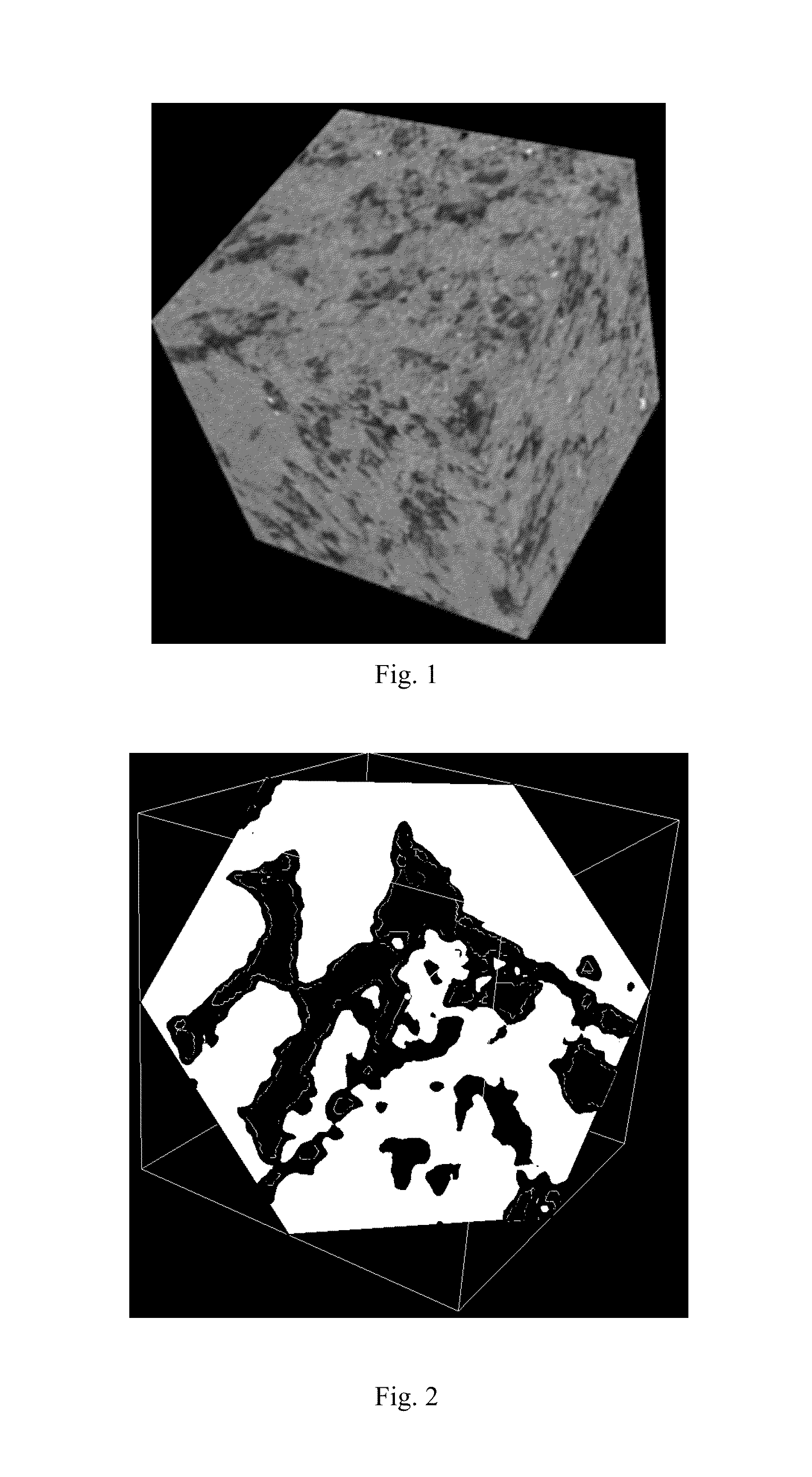
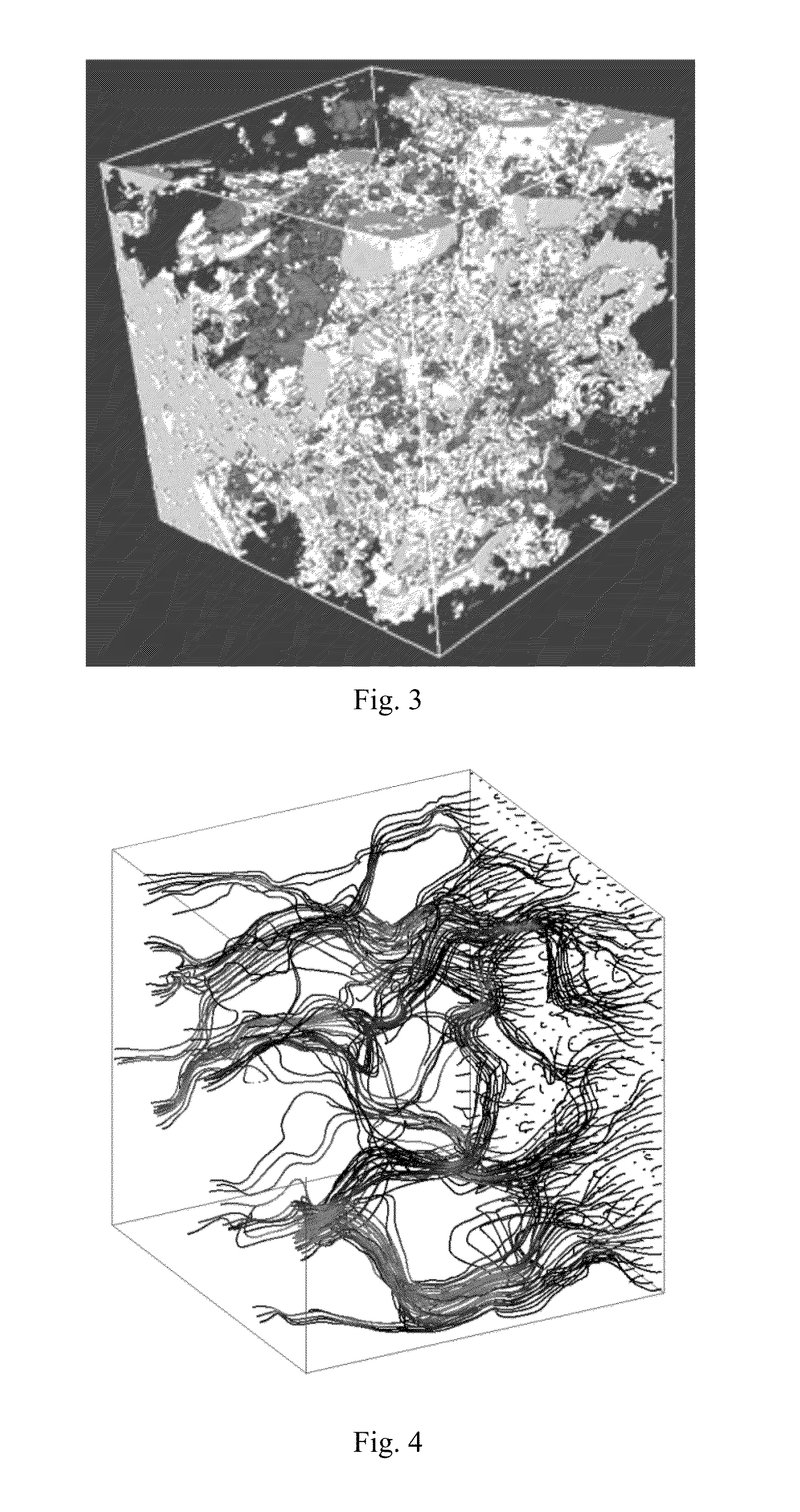
Embodiment Construction

[0034]In the description of the present invention, as an example the claimed technology is applied to the cylindrically shaped core sample. This fact obviously cannot be considered a factor limiting the scope of possible applications of the claimed method to any other designs and forms of porous media, including drill cuttings.

[0035]First of all, core is lifted to the surface in the process of drilling and taken to the laboratory, where typically a smaller size sample is cut out for further micro tomography investigation.

[0036]Further, tomographic study of the sample is performed with sufficient resolution (with the necessary size of the pixels on the tomographic image). The result is a set of sequential images of the core, each of which is represented by a set of pixels having different shades of gray—ranging from pure white to pure black. Herein white color corresponds to the maximum bulk density in the volume, black correspond to the minimum.

[0037]The next step is to distinguish ...


PUM


Abstract

The present invention relates to a method for producing a three-dimensional characteristic model of a rock sample for analysis of the spatial and physical characteristics of materials subsequent to the processing of images obtained by means of computer tomography. The method includes producing a three-dimensional tomographic image of a sample of material, identifying areas where the structure of the material is homogeneous, assigning a particular material density value to each such area, assigning a particular porosity value to each pixel, assigning a particular absolute permeability value to each pixel, forming a three-dimensional characteristic model on the basis of the porosity and permeability values of each pixel, and calculating the absolute permeability of the entire sample or of a portion thereof in any direction by means of computational fluid dynamics. The technical result is an increase in the precision and reliability of data obtained regarding the permeability characteristics of a sample of porous material, without the need to employ additional financial and labor resources.

Description

FIELD OF THE INVENTION[0001]The present invention relates to the field of study of porous materials and media properties. More specifically, the invention relates to the method for obtaining characteristic three-dimensional model of a rock sample for further study of its spatial physical properties based on the processed computed tomography (CT) images.BACKGROUND ART[0002]Oil and gas deposits lie at various depths in the porous rocks of Earth crust. One of the methods for studying productive formations is the examination of cores—cylindrical rock samples extracted in the process of drilling wells. Rock has multi-scale non-uniform structure. Core analysis allows addressing many crucial issues of field development: petroleum reserves evaluation, recovery method choice, field development economic evaluation, etc.[0003]Nowadays, petroleum engineers face increasingly complicated fields—carbonate formations, shale oil etc. that require more efficient recovery enhancement methods.[0004]Car...

Claims


Application Information

Patent Timeline
IPC IPC(8): G01V99/00G06F17/10
CPCG06F17/10G01V99/005G01N23/046G01N2223/616G01N2223/649G01N15/0826G01N15/088G01N2015/0846G06T17/05G01N2223/419G16C99/00G01V20/00
Inventor GRACHEV, EVGENIY ALEKSANDROVICHKULIKOV, VADIM GENNADIEVICHGORBIK, ANDREY PETROVICHKALASHNIKOV, GEORGIY ALEKSEEVICHSARATOV, ANTON ALEKSANDROVICHSHVARTSBERG, ALEKSANDR VLADIMIROVICH
Owner OBSCHESTVO S OGRANICHENNOY OTVETSTVENNOSTIU INTROVISION RESERCH & DEV
Learn More