
Crimp terminal, method of manufacturing crimp terminal, electrical wire connection structure, and method of manufacturing electrical wire connection structure

a technology of crimp terminal and crimp terminal, which is applied in the direction of connection contact material, connection effected by permanent deformation, line/current collector details, etc. it can solve the problems of easy corrosion of the crimp portion, increased temperature of the wire harness, and prone to electrical corrosion such as contact corrosion between dissimilar metals or the like, so as to improve the joint strength of the crimp terminal and enhance the joint strength of the fitting portion and the covered electrical wire connection portion

Active Publication Date: 2015-11-26
FURUKAWA ELECTRIC CO LTD +1
View PDF66 Cites 9 Cited by
  • Summary
  • Abstract
  • Description
  • Claims
  • Application Information

AI Technical Summary

Benefits of technology

The invention is a wire harness that prevents electrical corrosion and deformation of crimp terminals, which can occur due to environmental factors such as temperature variations and moisture. The crimp terminal is sealed and crimped to a covered electrical wire, which prevents moisture from entering the connection point and thus avoids electrical corrosion. The strength of the crimp terminal is increased by using a convex portion, which prevents deformation and breaking of the crimp terminal. The manufacturing process of the crimp terminal is not complicated and no complicated device is used. Overall, the invention improves the reliability of wire harnesses and enhances their durability under harsh environments.

Problems solved by technology

In addition, it is necessary to enhance fuel consumption of vehicles.
That is, the crimp portion is easily corroded when coming into contact with water or moisture.
When a wire harness is used in a vehicle, the usage environment of the wire harness is harsh, so that moisture or dust adheres to the wire harness or the temperature of the wire harness increases.
Therefore, when moisture or the like adheres to the connection portion between the core wire and the crimp terminal, electrical corrosion such as contact corrosion between dissimilar metals or the like is liable to occur.
The electrical corrosion causes contact failure between the core wire and the crimp terminal.
Therefore, there is a risk that the molded resin material deteriorates during use and the cut-off (water-stopping) performance degrades.
The crimp terminal disclosed in Patent Document 2 has a fitting portion functioning as a connector as well as the covered electrical wire connection portion to be connected to the covered electrical wire, and the conventional structure has a problem in joint strength between the fitting portion and the covered electrical wire connection portion.
As described above, the usage environment of the wire harness is harsh, and when the temperature greatly varies, there is a risk that cracks occur in the sealed portion or gaps occur among respective members due to the difference in expansion coefficient among the respective members or the like.
Furthermore, there is a risk that moisture reaches the connection portion between the core wire and the crimp terminal and thus electrical corrosion occurs.
Cracks or the like occur in the sealed portion, and electrical corrosion is liable to occur.
Deformation and breaking easily occur due to this stress concentration.
Specifically, when the copper-based material which has been conventionally used for the conductor of the covered electrical wire is replaced by aluminum-based material such as aluminum, aluminum alloy or the like and the conductor formed of aluminum-based material is crimped to the crimp terminal, there occurs a problem caused by a phenomenon that the aluminum-based material as base material is corroded due to the contact between the aluminum-based material and noble metal such as tin plating, gold plating, copper alloy or the like, that is, an electrical corrosion problem occurs.
As a result, sufficient electrically conductive function cannot be performed.
However, when the transition portion is lengthened or the transition portion is formed of one sheet of the flat plate, the strength is insufficient.

Method used


Image

  • Crimp terminal, method of manufacturing crimp terminal, electrical wire connection structure, and method of manufacturing electrical wire connection structure
  • Crimp terminal, method of manufacturing crimp terminal, electrical wire connection structure, and method of manufacturing electrical wire connection structure
  • Crimp terminal, method of manufacturing crimp terminal, electrical wire connection structure, and method of manufacturing electrical wire connection structure

Examples


Embodiment Construction

[0065]An embodiment according to the present invention will be described hereunder with reference to the drawings.

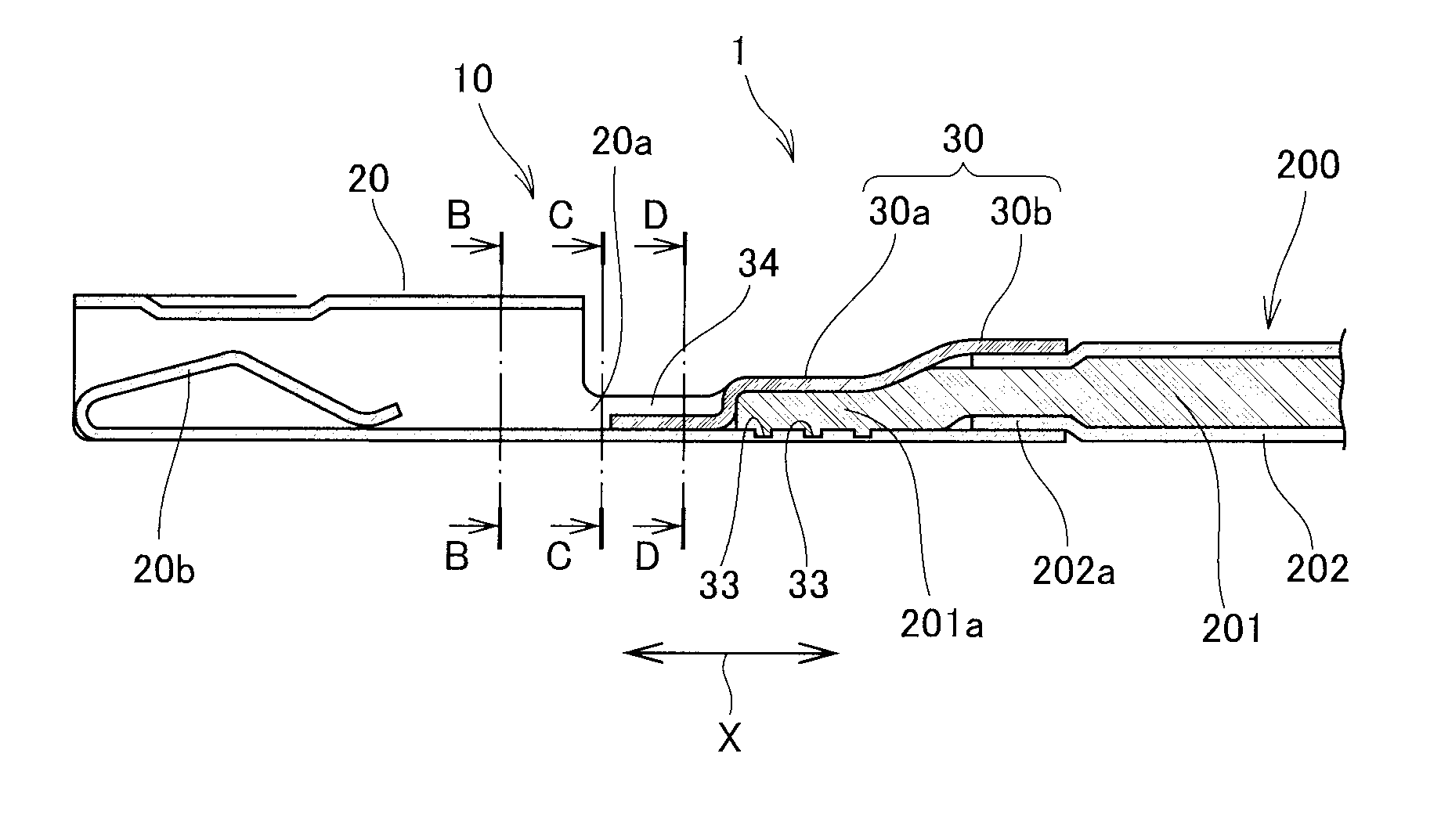
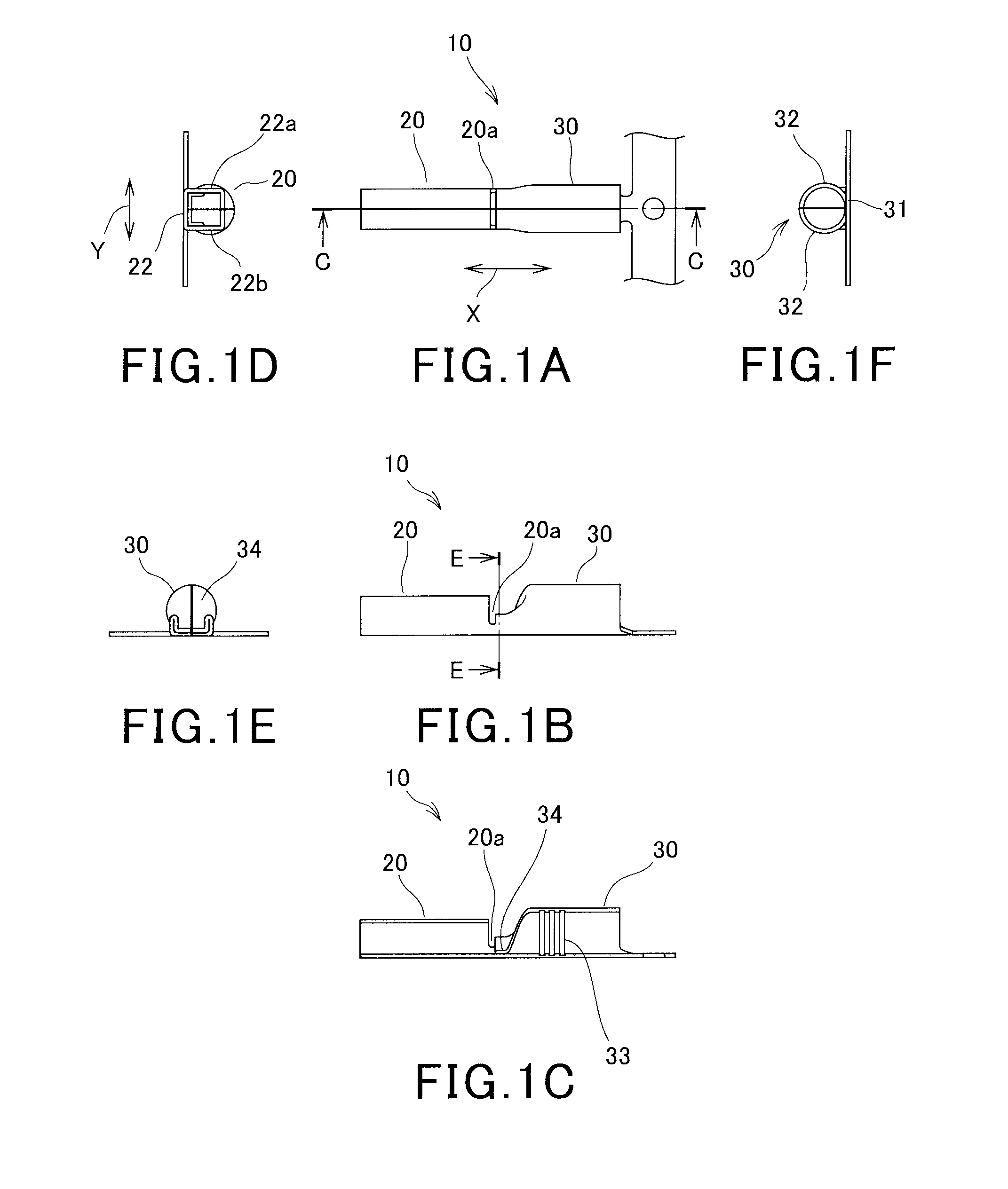
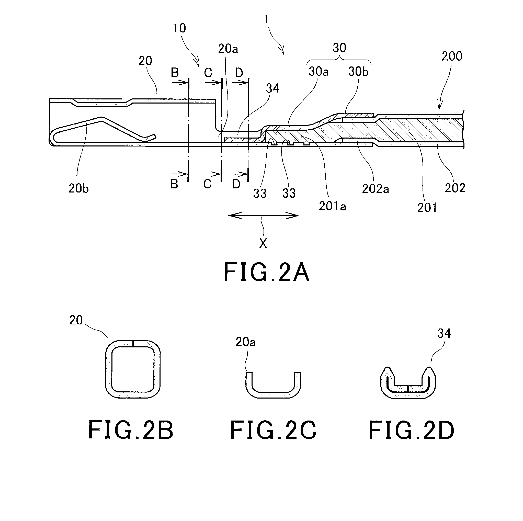
[0066]FIGS. 1A to 1F show a female type crimp terminal 10. The female type crimp terminal 10 has a box portion (fitting portion) 20 for allowing an insertion tab of a male type connector (not shown) to be inserted from the front side corresponding to the tip side in a longitudinal direction X of the female type crimp terminal 10 to the back side of the female type crimp terminal, and a crimp portion (electrical wire connection portion) 30 which is configured integrally with the box portion 20 and located at the back side of the box portion 20 through a transition portion 20a having a predetermined length. For convenience sake, the transition portion 20a is referred to in this specification. However, in this embodiment, the transition portion 20a is extremely short, and it seems as if it is not existent. As described later, the dimension of the transition portion 20a is s...


PUM

PropertyMeasurementUnit
areaaaaaaaaaaa
widthaaaaaaaaaa
lengthaaaaaaaaaa

Abstract

A crimp terminal that can maintain excellent water-stop performance over a long term and is enhanced in joint strength between a fitting portion and a covered electrical wire connection portion. The crimp terminal has a fitting portion at a tip thereof and an electrical wire connection portion at a rear end thereof, the electrical wire connection portion is configured in a tubular shape, a tip of the tube is crushed to be superimposed and closed, and a portion between the fitting portion and the electrical wire connection portion is formed by superimposing and bending two or more sheets of a plate material.

Description

BACKGROUND OF THE INVENTION[0001]1. Technical Field[0002]The present invention relates to a crimp terminal to be mounted to a connector or the like that serves to connect a wire harness for a vehicle, for example, a method of manufacturing the crimp terminal, an electrical wire connection structure and a method of manufacturing the electrical wire connection structure.[0003]2. Related Art[0004]A crimp terminal has a crimp portion to which a conductor of a covered electrical wire is electrically connected. After the covered electrical wire is inserted into the crimp portion, the crimp portion is swaged and crimped to the conductor to thereby connect the covered electrical wire. Such a crimp terminal is used for a wire harness that connects electrical components of a vehicle, for example. The wire harness comprises a bundle of plural covered electrical wires, and a connector is connected to the tip of the wire harness. As disclosed in JP-A-2002-367714, a crimp terminal is connected to...

Claims


Application Information

Patent Timeline
Patent Type & Authority Applications(United States)
IPC IPC(8): H01R4/18H01R43/048
CPCH01R4/18Y10T29/4922H01R43/048H01R4/187H01R4/70H01R4/62H01R4/20
Inventor KAWAMURA, YUKIHIROTONOIKE, TAKASHIYAMADA, TAKUROKOZAWA, MASAKAZUTAKAHASHI, DAISUKEKAWATA, MASAFUMIYAMAZAKI, TOMOHIROKOBAYASHI, HIROAKI
Owner FURUKAWA ELECTRIC CO LTD
Learn More