Illuminated endoscopic pedicle probe with dynamic real time monitoring for proximity to nerves

a pedicle probe and real-time monitoring technology, applied in the field of surgical instruments, can solve the problems of dural or neural injury, dural or medial penetration of pedicle cortex and dural or medial penetration, no direct confirmation, etc., and achieve the effect of avoiding rupture, avoiding parallax, and directly and accurately determining

Inactive Publication Date: 2015-12-03
OPTICAL SPINE LLC
View PDF17 Cites 65 Cited by
  • Summary
  • Abstract
  • Description
  • Claims
  • Application Information

AI Technical Summary

Benefits of technology

[0033]The endoscopic pedicle probe of the invention puts the surgeon “in the pedicle” with the use of endoscopy and avoids breaches by using electromyography. The positioning of the probe can be directly and accurately determined during surgery, and there is no question as to whether the screw will be too medial, lateral, cranial, caudal, or deep. The surgeon will know if the wall of the pedic...

Problems solved by technology

These conventional modalities require a steep learning curve, and improper or inaccurate manipulation of the probe and placement of the pedicle screw can result in caudal or medial penetration of the pedicle cortex and dural or neural injury.
With conventional pedicle probes there is no direct way to confirm that the hole was made within the pedicle and that the screw will be placed completely inside the pedicle.
Surrounding structures can be injured if a portion of the screw is placed outside of the pedicle.
There can be nerve root injury, epidural vessel injury, or spinal fluid leakage caused by a misplaced screw.
Although the earlier embodiments of applicant's invention cured many of the deficiencies of prior ...

Method used


Image

  • Illuminated endoscopic pedicle probe with dynamic real time monitoring for proximity to nerves
  • Illuminated endoscopic pedicle probe with dynamic real time monitoring for proximity to nerves
  • Illuminated endoscopic pedicle probe with dynamic real time monitoring for proximity to nerves

Examples


first embodiment

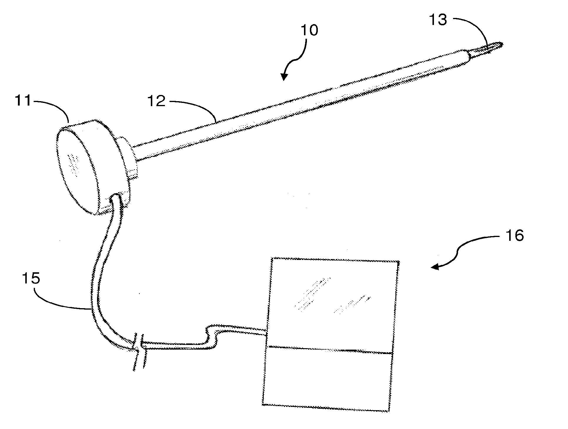
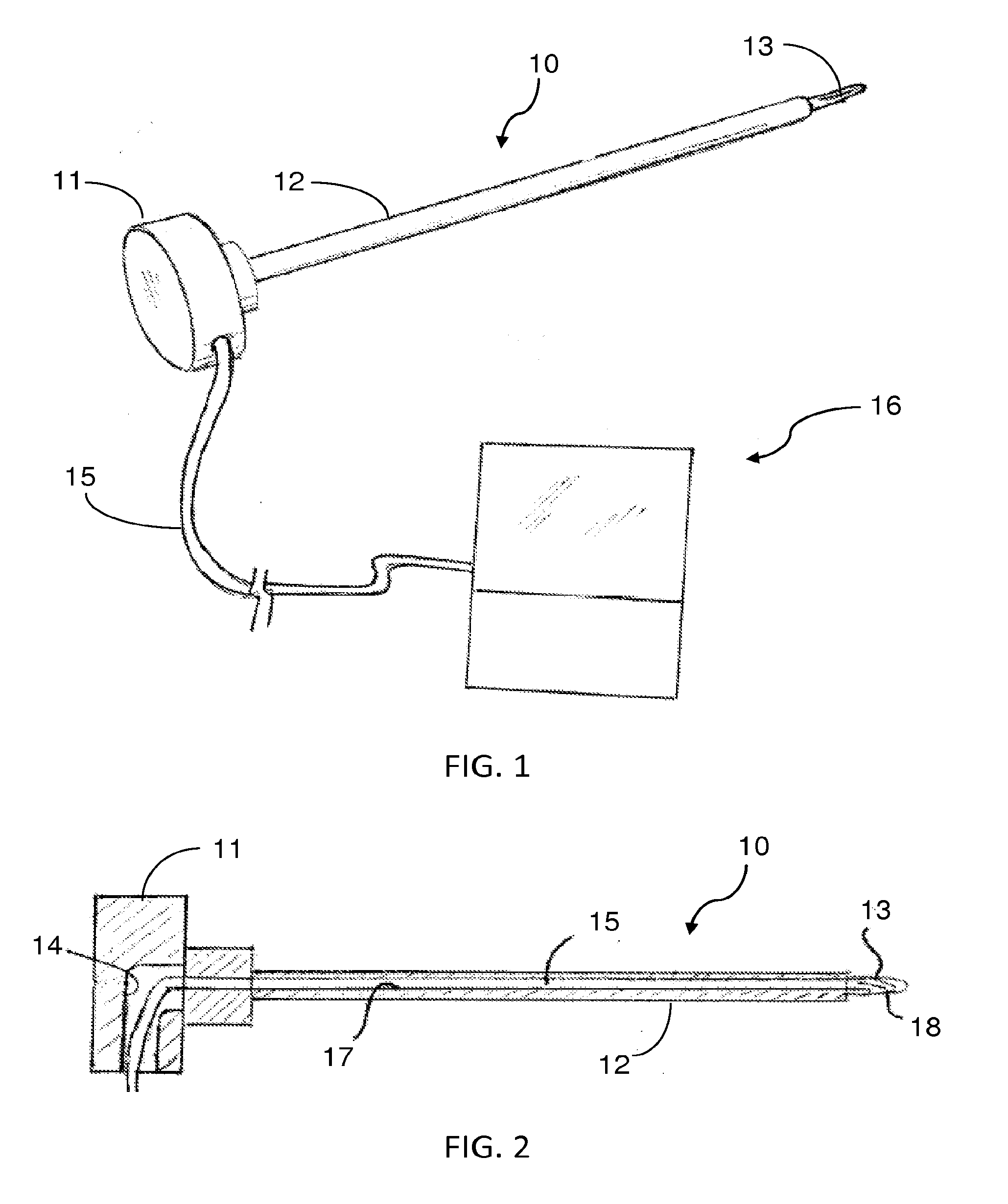
[0065]Referring more specifically to the drawings, a pedicle probe according to the invention is depicted at 10 in FIG. 2. The probe has a disc-shaped head 11 on its proximal end that is about two inches in diameter, and a metal shaft 12 projecting from the center of one side thereof. A reduced diameter tip 13 on the distal end of the shaft is configured to act as a reamer, i.e., it may have a fluted configuration as found on drill bits. In use, a surgeon places the disc-shaped head 11 in the palm of his or her hand, with the shaft extending forwardly. The tip is then pushed against the pedicle while the probe is being rotated back and forth about the longitudinal axis of the shaft to form a hole in the pedicle for reception of a pedicle screw. See, for example, FIGS. 12-19.

[0066]In the embodiment shown in FIGS. 1 and 2, the disc-shaped head 11 of the probe 10 has an opening 14 formed in it for receipt of an endoscope 15 with integrated illumination means, such as the Medigus LEDpro...

second embodiment

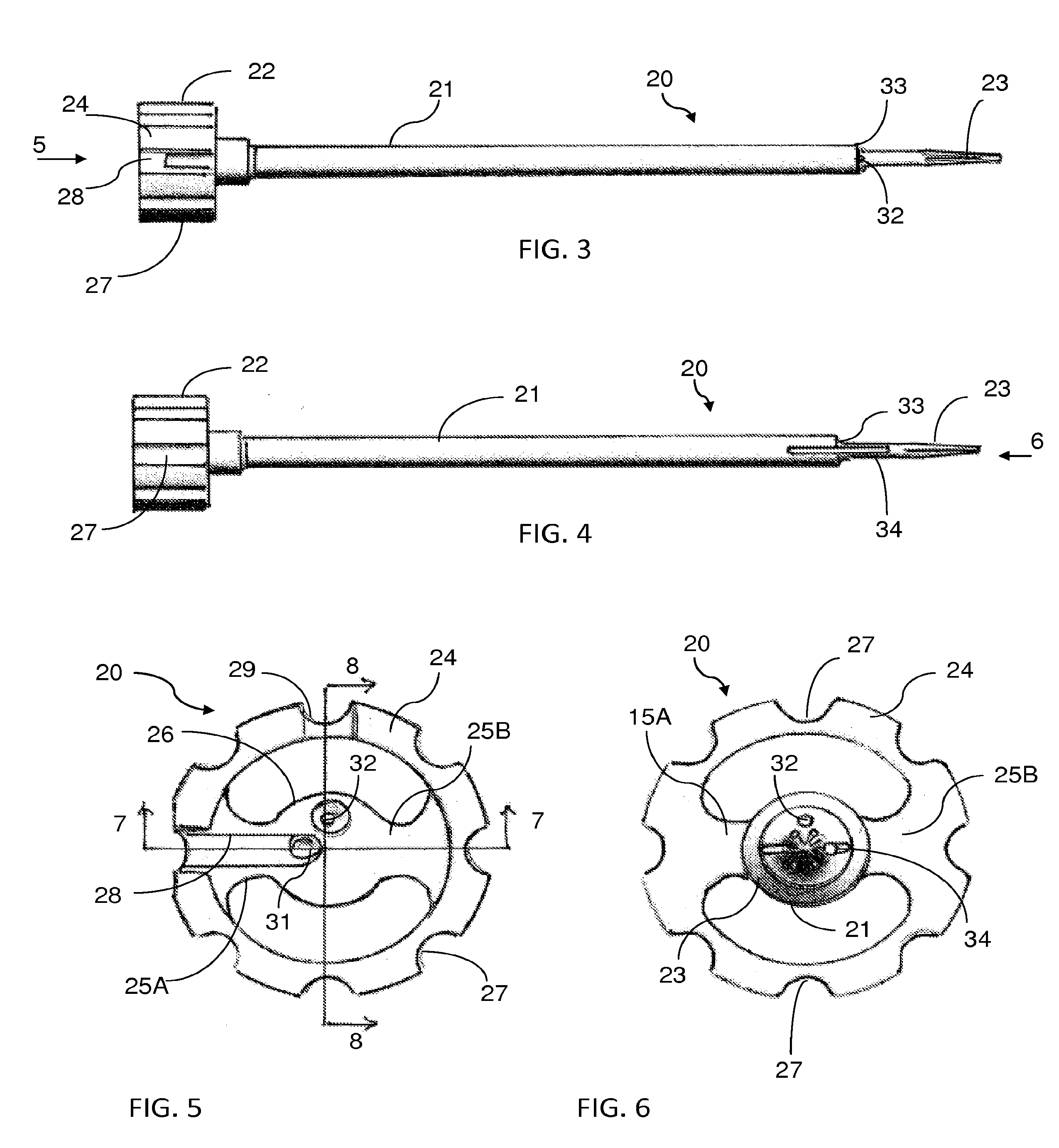
[0068]endoscopic pedicle probe according to the invention is indicated generally at 20 in FIGS. 3-11. Although not shown, an endoscope with integrated illumination means as described in connection with the FIG. 1 embodiment, i.e. the Medigus LEDprobe, may also be used in this form of the invention. This form differs from that shown in FIG. 1 in that the tip 23 can be configured to position the camera 25 for providing a 90° view or a 45° forward view or a 0° view straight ahead. Thus, by selection of an appropriate probe, or by appropriate manipulation of a probe, the surgeon can obtain a direct visual indication of the exact position of the probe in the pedicle and of the pedicle itself and surrounding structure. As depicted in these figures, the camera is placed rearwardly of the distal point of the end to protect it when the probe is pressed against and pushed through hard bony tissue. An obturator, not shown, may be provided to close the opening through the side of the tip and pr...

third embodiment

[0074]probe according to the invention is shown in FIGS. 20 and 21. In this embodiment, two endoscopes 40 and 41 are provided in the probe. One of the endoscopes 41 has its camera 25 positioned at the distal end of the tip 43 in a zero degree forwardly facing orientation. The other endoscope 40 has its camera 25 positioned at the distal end 44 of the probe shaft 45 and oriented in a camera window slot 46 to provide about a 70° view looking at the side of the pedicle wall. The endoscopes 40 and 41 preferably have an illuminating means integrated with them, as in the Medigus LEDprobe discussed above, and / or a separate light 47 may be provided. A saline rinse port 48 also preferably is provided at the distal end of the probe shaft to rinse away debris during use of the probe to keep the field of vision clear.

[0075]A fourth embodiment 50 of pedicle probe according to the invention is shown in FIGS. 22-25. In this form of the invention, rather than extend bores longitudinally through the...


PUM


Abstract

An endoscopic pedicle probe for use during spinal surgery to form a hole in a pedicle for reception of a pedicle screw has an enlarged proximal end for cooperation with the hand of the surgeon and an elongate shaft terminating in a distal tip that may be pushed through the pedicle to form the hole. An integrated endoscope and light extend through the shaft to enable the surgeon to visually observe the target area, and a conduit extends through the shaft to convey a fluid to irrigate the target area. In a preferred form the probe is connected with an electromyographic or mechanomyographic monitoring system to alert the surgeon when a breach is about to occur. In a further embodiment, two endoscopes are associated with the probe. The complete probe may be disposable, or just the tip may be detachable for disposal or replacement.

Description

[0001]This application is a continuation-in-part of U.S. patent application Ser. No. 14 / 289,795, filed May 29, 2014, which claims the benefit of U.S. provisional patent application Ser. No. 61 / 955,895, filed Mar. 20, 2014, and is a continuation-in-part of U.S. patent application Ser. No. 13 / 728,987, filed Dec. 27, 2012, which in turn claims the benefit of U.S. provisional patent application Ser. No. 61 / 647,747, filed May 16, 2012.TECHNICAL FIELD[0002]This invention relates generally to surgical instruments. More specifically, the invention relates to a pedicle probe for use in forming holes in a vertebral pedicle in preparation for pedicle screw insertion. According to one feature of the invention the probe incorporates at least one endoscope to enable the surgeon to see the area being treated. A light is integrated with the probe to illuminate the area being treated, and in a preferred embodiment irrigation means is associated with the probe to flush debris away from the area being...

Claims


Application Information

Patent Timeline
IPC IPC(8): A61B17/16A61B1/06A61B1/015A61B17/17A61B5/11A61N1/36A61B17/86A61B1/00A61B5/0488
CPCA61B17/1671A61B1/00087A61B1/00045A61B1/06A61B1/015A61B5/0488A61B2017/00075A61N1/36A61B17/86A61B17/1732A61B17/1757A61B2017/0262A61B2017/00039A61B5/1107A61B1/3135A61N1/0551A61B1/05A61B1/07A61B5/6848A61B5/6878A61B5/066A61B5/067A61B5/1109A61B2217/007A61B5/389A61N1/36031A61B5/395
Inventor JACKSON, III, AVERY M.
Owner OPTICAL SPINE LLC
Why Eureka
Try Eureka