
Vehicle-mounted power supply device and vehicle comprising power supply device

a power supply device and vehicle technology, applied in the direction of nickel accumulators, cell components, batteries, etc., can solve the problems of increased cost, loss, and complicated circuit, and achieve the effect of efficient heat radiation

Inactive Publication Date: 2015-12-03
SANYO ELECTRIC CO LTD
View PDF6 Cites 8 Cited by
  • Summary
  • Abstract
  • Description
  • Claims
  • Application Information

AI Technical Summary

Benefits of technology

The present invention relates to a power supply device for vehicles, which can connect to a lead-acid battery of 12V. The device includes a battery block with multiple secondary batteries that can charge and discharge, a circuit board for controlling the batteries, and a storage case for storing the battery block and circuit board. The secondary batteries are connected in series to increase the overall voltage. The device also has a thermal insulation dividing wall to protect the circuit board from heat generation by the battery block. A cooling air passage is formed to efficiently radiate heat, and each battery has a curved covering surface to enhance heat radiation. The secondary batteries are held in a horizontal posture to prevent short circuit. The technical effects of this invention include easy adjustment of required voltage, improved heat radiation, and enhanced safety.

Problems solved by technology

However, as the voltage of the lithium ion secondary battery cell is normally 3.6 V, and even in the series connection, for example, it has 10.8 V of 3 series connection, 14.4 V of 4 series connection, and any one coincides with 12 V, and then it by itself cannot be connected to the lead-acid battery of 12 V. Therefore, a voltage converting circuit which increases or decreases the total voltage of the sub-battery including the lithium ion secondary batteries, is necessary, and it complicates a circuit, and it increases cost.
In addition, a loss occurs by the voltage conversion, and such a loss is consumed as heat, and then the temperature of the sub-battery is increased.

Method used


Image

  • Vehicle-mounted power supply device and vehicle comprising power supply device
  • Vehicle-mounted power supply device and vehicle comprising power supply device
  • Vehicle-mounted power supply device and vehicle comprising power supply device

Examples


embodiment 1

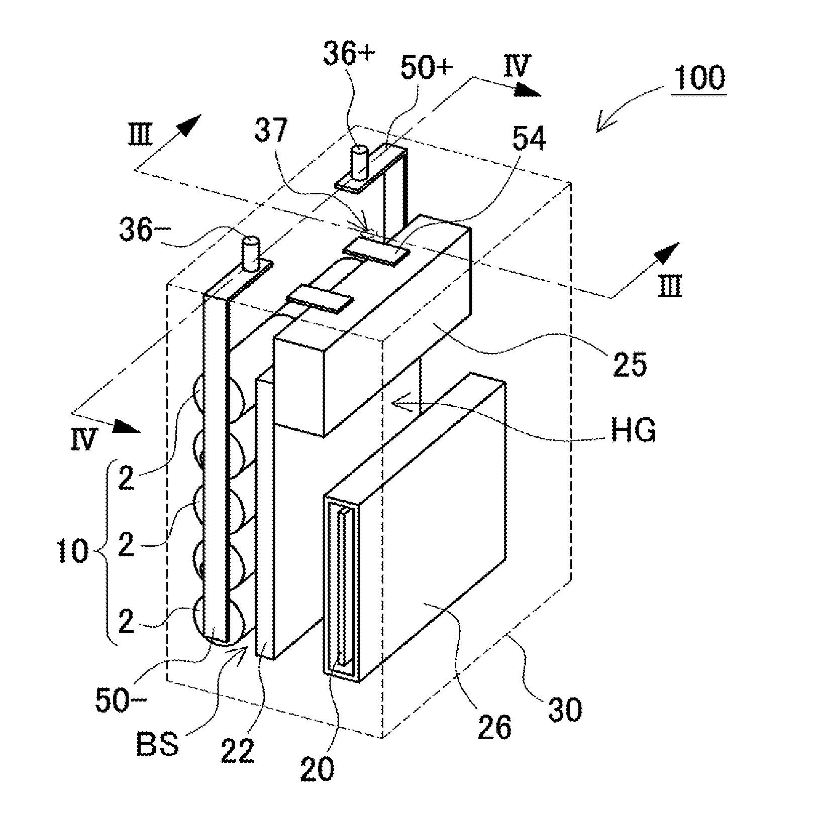
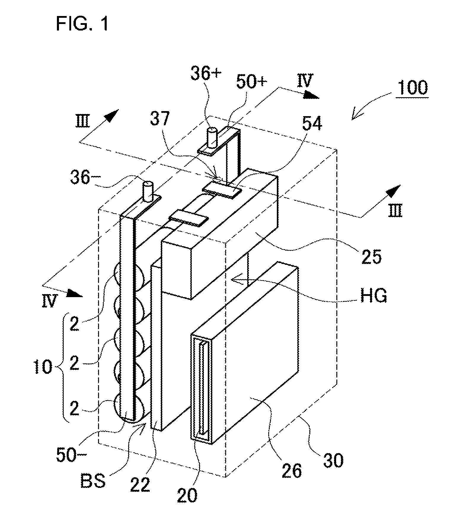
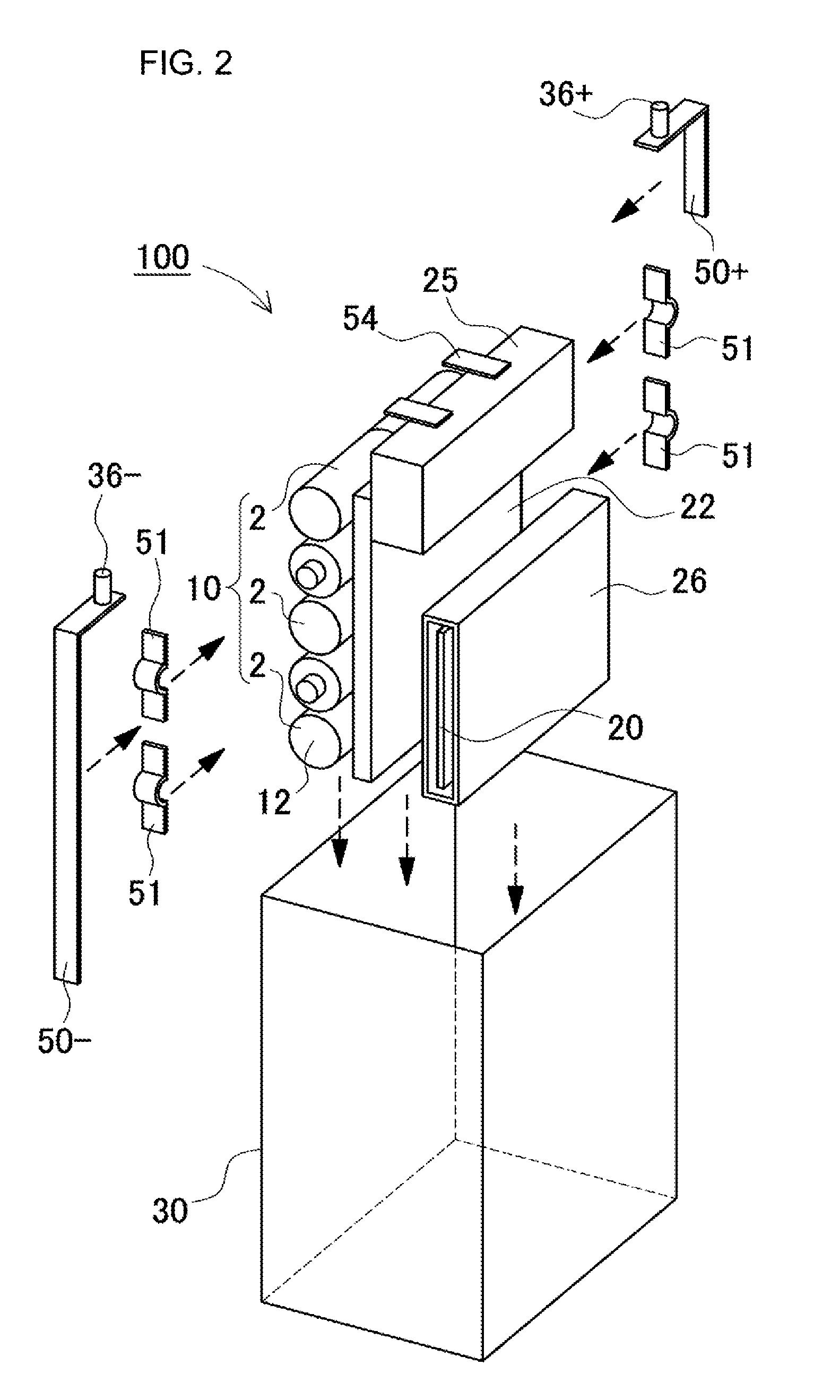
[0028]A perspective view showing a power supply device 100 related to one embodiment 1 of the present invention is shown in FIG. 1. An exploded perspective view of the power supply device 100 is shown in FIG. 2. The internal structure of the power supply device 100 is shown in sectional views of FIG. 3 and FIG. 4. The power supply device 100 shown in these figures has a battery block 10 including a plurality of secondary batteries 1, a circuit board 20 electrically connected to the battery block 10, a storage case 30 which stores the plurality of the secondary batteries 1 and the circuit board 20, and a pair of output terminals 36 which output total voltage of the battery block 10. In FIG. 1, the storage case 30 is shown in a dashed line in order to show the internal structure of the power supply device 100. The power supply device 100 for a vehicle as the sub-battery, as shown in FIG. 8 described below, is connected in parallel to the battery of 12 V for an electric equipment devic...


PUM

PropertyMeasurementUnit
nominal voltageaaaaaaaaaa
total voltageaaaaaaaaaa

Abstract

A power supply device for a vehicle connectable in parallel to a lead-acid battery of 12 V, comprises a battery block including a plurality of secondary batteries capable of charging and discharging, a circuit board having an electric circuit configured to control the charging and discharging of the battery block, and a storage case for storing the battery block and the circuit board. The battery block is configured to connect an N number (N being a natural number) of nickel hydride batteries as the secondary batteries in series.

Description

TECHNICAL FIELD[0001]The present invention is related to a vehicle-mounted power supply device and a vehicle comprising the power supply device, for example, a battery system for a vehicle where a lead-acid battery and a sub-battery are connected in parallel, and a vehicle incorporating this battery system.BACKGROUND ART[0002]A conventional vehicle incorporates a lead-acid battery having a nominal voltage 12V of a lead-acid storage battery, and a large vehicle incorporates a battery having a nominal voltage 24 V where 2 pieces of the lead-acid batteries of 12 V are connected in series. The lead-acid battery is charged by an alternator of the vehicle, and supplies power to electric equipment devices or a starter motor. The lead-acid battery has a small discharging resistance, but has a large charging resistance, and then it is difficult to efficiently charge it. In order to improve this problem and enlarge the battery capacity (Ah) with respect to volume and weight, the battery syste...

Claims


Application Information

Patent Timeline
Patent Type & Authority Applications(United States)
IPC IPC(8): B60L11/18H01M10/625H01M10/6563H01M10/46H01M50/24H01M50/249H01M50/284H01M50/51H01M50/519
CPCB60L11/1877H01M10/46H01M2220/20H01M10/6563B60L11/1816H01M10/625B60R16/04H01M10/06H01M10/30H01M10/345H01M10/425H01M10/643H01M10/6561H01M10/613H01M10/658B60L50/66Y02E60/10Y02T10/70H01M50/249H01M50/519B60L50/64H01M50/284H01M50/51H01M50/24
Inventor SAKATA, HIDEKINAKAJIMA, KAORUTSUNESADA, AKINOBU
Owner SANYO ELECTRIC CO LTD
Learn More