
Hot and cold temperature supply device

Active Publication Date: 2015-12-03
HAHN THOMAS
View PDF0 Cites 5 Cited by
  • Summary
  • Abstract
  • Description
  • Claims
  • Application Information

AI Technical Summary

Benefits of technology

The patent describes a heating and cooling supply device that can efficiently generate and store usable heat or cooling by using a temperature-dependent stratification of the heat transfer medium. The device has a compact construction, which allows for a smaller proportion of oil in the working substance and reduces flow losses, resulting in a more efficient compressor power requirement.

Problems solved by technology

This radiation causes cell damage, with adverse effects on living organisms and plants.
However, the technical application of such working substances is not easy.
Ammonia, for example, due to its toxicity, cannot be used in devices operated in enclosed spaces.
Propane and butane are extremely flammable, and the use of CO2 in the trans-critical region causes high pressures in the refrigeration circuit.
For example, toxic ammonia or flammable butane or propane can escape if there are leaks or damage to pipework or other components of cycle process plants or heat pumps.
Cycle process plants with larger amounts of these working substances are currently not operated in enclosed or inhabited buildings.
For example, CO2 is also toxic if it escapes into a cellar.
Concentrations of more than 8% in the air breathed are fatal.
In addition to the so-called “natural refrigerants”, the newly developed fluorohydrocarbon-based working substances, e.g. HFO-1234yf, are also toxic and highly flammable.
These losses are essentially mechanical and thermal losses together with flow losses and losses in the working substance.
In practice, the design of such plants is very complex and error-prone.
Therefore, plants coupled in this way are offered extremely rarely.
Cycle process plants according to the current state of the art that are installed inside storage tank in this unusual way cannot function effectively without a whole series of modifications and additional control parameters.
For example, in contrast to plants according to the prior art, there is the problem of overheating in passive operation as a heat store.
A temperature rise inside the storage device necessarily also causes temperature and pressure increases in the components of the shut-down cycle process plant that carry working substance.
Depending on the working substance used, pressure increases can cause damage to materials.
1. Limitation of the storage device temperature even in passive operation, i.e. without using the cycle process plants. The maximum temperature depends on the permissible operating pressures of the working substance in the components.
2. Coordinating all the working substances used with the reactants and binding agents used in the heat transfer medium at the same time. If two or more cycle process plants are used, these must be coordinated in such a way that even the simultaneous escape of different working substances in the event of damage can be managed chemically in a controlled way.
3. The coordination of two or more cycle process plants in the storage device takes place with the smallest possible temperature rise in the individual cycle process plants. E.g. by a stepwise temperature rise distributed across the cycle process plants involved, and the corresponding arrangement of heat exchangers to bring external heat into or out of storage in the storage device.
4. The combination of different kinds of cycle process plants requires special design effort. For example, the combination of an electrically driven cycle process plant using ammonia as the working substance and a diffusion-absorption heat pump using an ammonia / water “refrigeration cycle”. Individual cycle process plants can be brought into operation selectively for different temperatures to be supplied by the system. Advantageously, the characteristic diagrams of the individual refrigeration cycle processes are saved in a controller device according to an aspect of the invention for this purpose. Such an option enables the most favorable cycle process plant operating conditions to be used in each case. The choice of operation and of the duration of operation of the respective cycle process plant takes place depending on the required useful cooling or quantities of heat and their temperature. The temperature of the external heat exchangers and their heat capacity is taken into account at the same time. The control of the respective device takes place according to the principle that the direct use of external heat or “cooling” from the external heat exchangers must take place before the cycle process plants are used. Thereafter, the cycle process plants are used stepwise or in a time-cycled manner to achieve the temperatures and amounts of heat required by the system.

Method used


Image

  • Hot and cold temperature supply device
  • Hot and cold temperature supply device
  • Hot and cold temperature supply device

Examples


Embodiment Construction

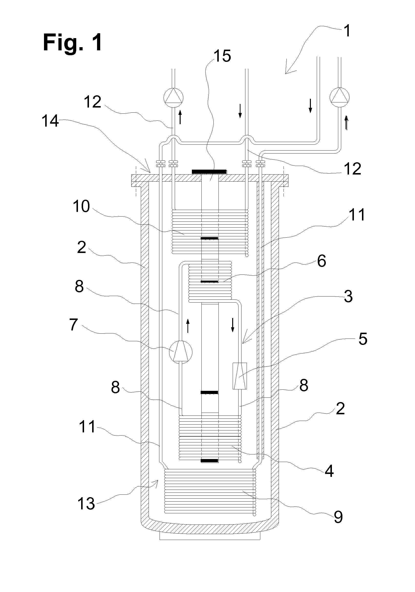
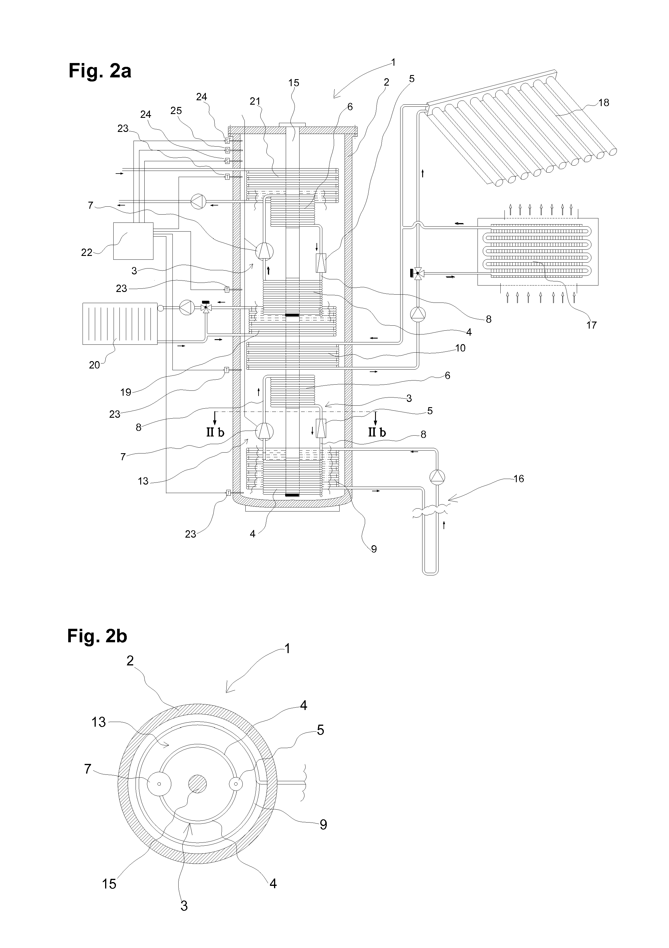
[0129]FIG. 1 shows a diagrammatic representation of a heating and cooling supply device 1 with a cycle process 3 arranged inside a storage tank 2. The cycle process 3 has an evaporator 4, a restrictor 5, a condenser 6 and a compressor 7, these components being interconnected via pipes 8.

[0130]Inside the storage tank 2, there are also provided a first heat exchanger 9 arranged in a lower region of the storage tank 2 and a second heat exchanger 10 arranged in an upper region of the storage tank. The first heat exchanger 9 is connected via pipes 11 to a thermal heat exchanger, not shown, e.g. a solar installation. The second heat exchanger 10 is connected via pipes 12 to a heat exchanger, e.g. a heating installation.

[0131]Useful heat from the thermal solar installation is fed via the first heat exchanger 9 into a heat transfer medium 13 arranged in the storage tank 2. A temperature level of the heat transfer medium 13 is raised by means of the heat pump 3 to such an extent that heat to...


PUM


Abstract

A device is provided for supplying heating and cooling, the device having a heat transfer medium arranged in the interior of a storage tank and having at least one cycle process plant operated using a working substance. The heat transfer medium has a lower temperature in a bottom region of the interior than in a region of the interior arranged thereabove. All the components of the cycle process plant that contain the working substance are arranged in the interior. The components of the cycle process plant arranged inside the storage tank are surrounded by the heat transfer medium. The heat transfer medium has constituents to bind or convert the working substance. The amount of the constituent as a proportion of the heat transfer medium is dimensioned in such a way that the working substance contained in the cycle process plant can be completely bound or converted by the constituent after an escape from the cycle process plant.

Description

BACKGROUND AND SUMMARY[0001]The invention relates to a device for supplying heating and cooling having a heat transfer medium arranged in the interior of a storage tank and haying at least one cycle process plant operated using a working substance, whereby the heat transfer medium has a lower temperature in a bottom region of the interior than in a region of the interior arranged thereabove and whereby the components of the cycle process plant are arranged in the interior.[0002]Definition of terms for the terms Cycle Process Plant, Working Substance and Heat Transfer Medium:[0003]The term Cycle Process Plant in the present context denotes all refrigeration cycle processes and other thermal cycle processes, for example operated by means of a gas. Refrigeration cycle processes in the present context comprise all cycle processes operating in a counter-clockwise direction in which the compression takes place mechanically or thermally. These include refrigeration cycle processes with a w...

Claims


Application Information

Patent Timeline
IPC IPC(8): F24F1/02F24H4/04F24F1/029F24F1/0323F24F1/0358
CPCF24H4/04F24F1/02F24H7/04F24D11/0221F24D2200/126F24D2220/08F24D2220/10F25B2400/071Y02B10/20Y02B10/70F25B15/04F25B25/005F25B27/005F25B30/04F25B30/06F25B2339/047F25B2400/06F25B2400/24B60H1/00492F28D20/0039Y02E60/14F24D3/08F24F1/029F24F1/0323F24F1/0358Y02B30/12
Inventor HAHN, THOMAS
Owner HAHN THOMAS
Learn More