
Electronic comparison systems

a comparison system and electronic technology, applied in the field of electronic comparison systems, can solve the problems of high static power consumption, prohibitively high energy and real-estate costs of conventional digital processing techniques for such tasks, and achieve the effect of improving the way of comparing and storing values, and improving the wta circui

Active Publication Date: 2015-12-03
PURDUE RES FOUND INC
View PDF17 Cites 53 Cited by
  • Summary
  • Abstract
  • Description
  • Claims
  • Application Information

AI Technical Summary

Benefits of technology

The patent text describes a way to compare signals using a method that consumes less power and takes up less space. This makes it possible to use memories and neural networks in a wider range of applications. The main technical effect is that it provides a more efficient way to compare signals, which can potentially expand the capabilities of these technologies.

Problems solved by technology

Use of conventional digital processing techniques for such tasks incurs prohibitively high energy and real-estate costs, due to the number of computations involved.
However, use of multiple analog blocks for large scale RCNs may lead to high static power consumption.
Moreover, with technology scaling, the impact of process variations upon analog circuits becomes increasingly more prominent, resulting in lower resolution for signal amplification and processing.
This limits scalability of analog approaches.
Hence, the conventional analog circuits may fail to exploit the RCN technology for energy efficient, non-Boolean computing.
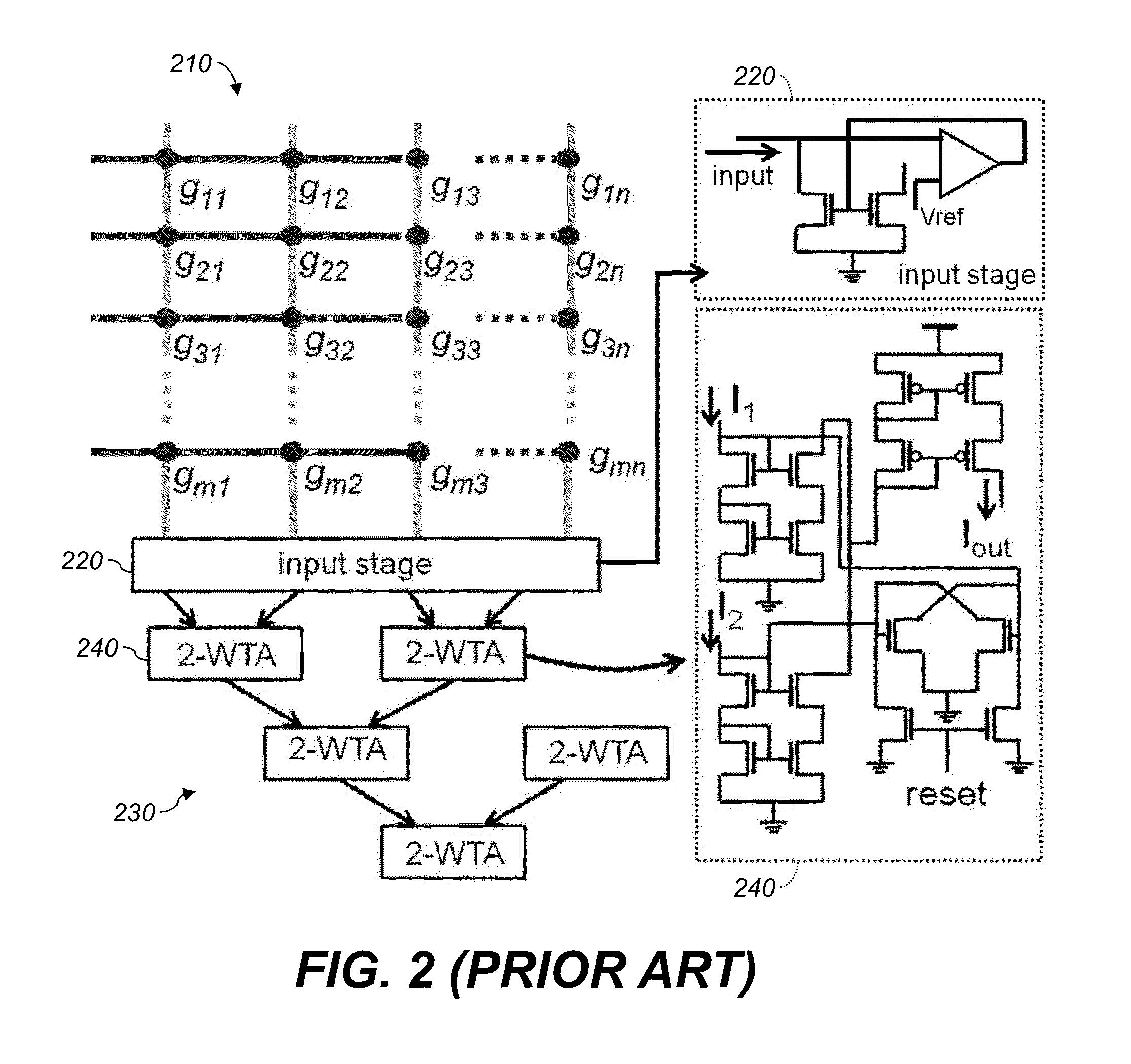
With increasing number of inputs to the WTA, the numbers of stages and nodes in the binary WTA tree 230 increase, leading to larger delay and area.
Therefore the area required increases steeply, and the time required also increases steeply.
In general, the use of such analog WTA circuits leads to large static power consumption.
In fact, the power consumption of an analog WTA unit can be several times larger than the RCN itself.
Moreover, the performance of such current-mirror based circuits is limited by random mismatches in the constituent transistors and other non-idealities, e.g., channel length modulation, that introduce mismatch in different current paths.
This leads to increased parasitic capacitances and thus lower operating frequency for a given static power.
Special techniques to enhance the precision of current mirrors have been proposed in literature, but they introduce significant overhead in terms of power consumption and area complexity.
Voltage-mode processing can also be employed in an RCN; however, it can incur additional overhead due to current to voltage conversion and subsequent amplifications.
This can incur larger mismatch, non-linearity and power consumption.
Accordingly, conventional mixed-signal CMOS design techniques may not be able to leverage the emerging nano-scale resistive memory technology for memory based computing.

Method used


Image

  • Electronic comparison systems
  • Electronic comparison systems
  • Electronic comparison systems

Examples


Embodiment Construction

[0050]Throughout this description, some aspects are described in terms that would ordinarily be implemented as software programs. Those skilled in the art will readily recognize that the equivalent of such software can also be constructed in hardware, firmware, or micro-code. Because data-manipulation algorithms and systems are well known, the present description is directed in particular to algorithms and systems forming part of, or cooperating more directly with, systems and methods described herein. Other aspects of such algorithms and systems, and hardware or software for producing and otherwise processing signals or data involved therewith, not specifically shown or described herein, are selected from such systems, algorithms, components, and elements known in the art. Given the systems and methods as described herein, software not specifically shown, suggested, or described herein that is useful for implementation of any aspect is conventional and within the ordinary skill in ...


PUM


Abstract

An electronic comparison system includes input stages that successively provide bits of code words. One-shots connected to respective stages successively provide a first bit value until receiving a bit having a non-preferred value concurrently with an enable signal, and then provide a second, different bit value. An enable circuit provides the enable signal if at least one of the one-shots is providing the first bit value. A neural network system includes a crossbar with row and column electrodes and resistive memory elements at their intersections. A writing circuit stores weights in the elements. A signal source applies signals to the row electrodes. Comparators compare signals on the column electrodes to corresponding references using domain-wall neurons and store bit values in CMOS latches by comparison with a threshold.

Description

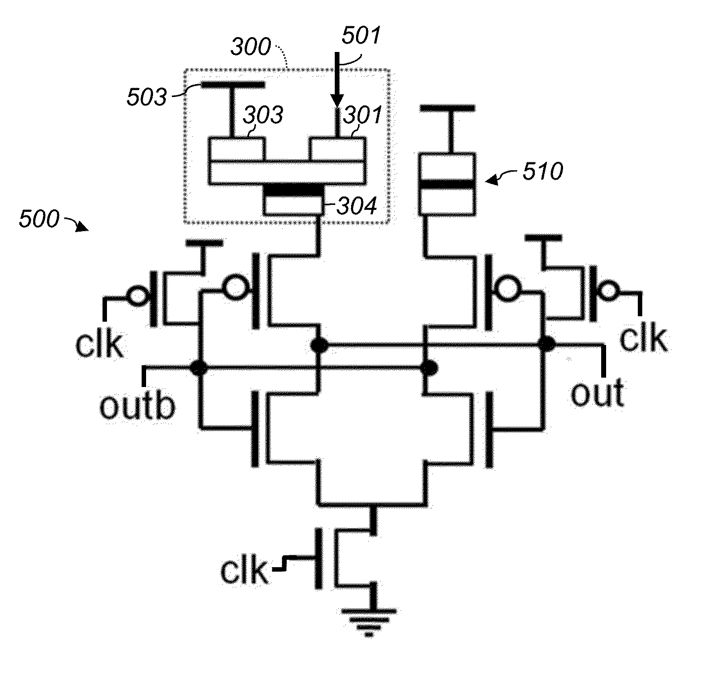
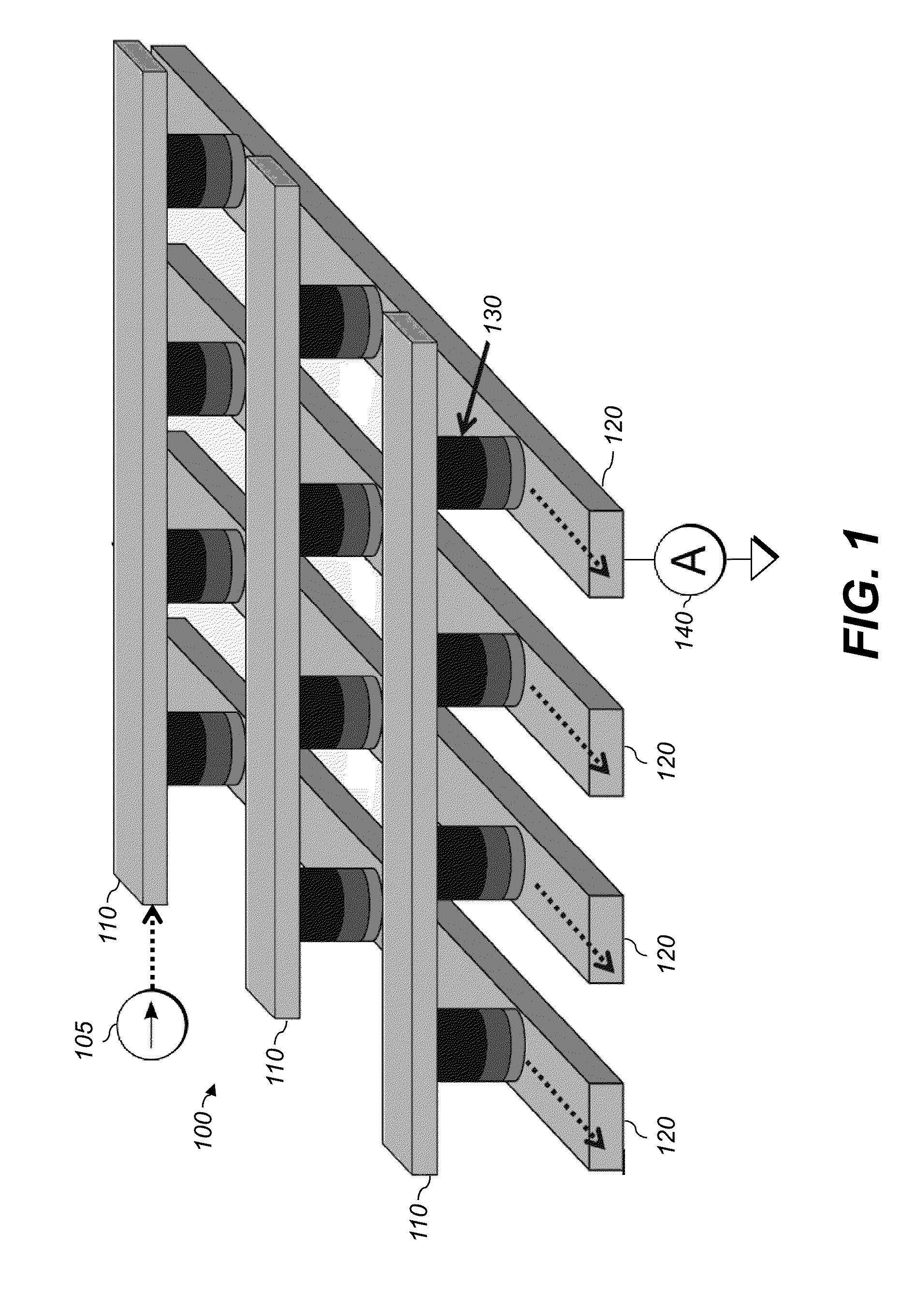
STATEMENT OF FEDERALLY SPONSORED RESEARCH OR DEVELOPMENT[0001]This invention was made with Government support under Contract No. 2013-MA-2381 awarded by the Defense Advanced Research Projects Agency. The government has certain rights in the invention.TECHNICAL FIELD[0002]The present application relates to electronic systems, and particularly to such systems for performing comparisons of signals or data.BACKGROUND[0003]In recent years several device solutions have been proposed for fabricating nano-scale programmable resistive elements, generally categorized under the term “memristor.” Of special interest are those which are amenable to integration with state of art CMOS technology, like memristors based on Ag—Si filaments. Such devices can be integrated into metallic crossbars to obtain high density resistive crossbar networks (RCN; also referred to as “resistive crossbar memory,” RCM).[0004]FIG. 1 is a perspective of an exemplary resistive crossbar network 100. It includes row elec...

Claims


Application Information

Patent Timeline
IPC IPC(8): G06N3/04H03M1/38G06N3/08G11C13/00
CPCG06N3/04G06N3/08H03M1/38G11C13/004G11C11/54G11C13/0007G11C15/02G11C15/046G11C11/161G11C11/1673G11C11/1675G11C11/1693G06N3/063G11C11/16G11C13/0069H03K3/356104H03M1/46
Inventor ROY, KAUSHIKSHARAD, MRIGANK
Owner PURDUE RES FOUND INC
Learn More