
Optical guided vacuum assisted biopsy device

a vacuum assisted and optical guide technology, applied in the field of medical devices, interventional devices, surgical instruments, etc., can solve the problems of not being able to reliably define and not being able to accurately diagnose the end point of the procedur

Active Publication Date: 2015-12-17
KONINKLJIJKE PHILIPS NV
View PDF1 Cites 38 Cited by
  • Summary
  • Abstract
  • Description
  • Claims
  • Application Information

AI Technical Summary

Benefits of technology

The patent text describes an interventional device that can help a physician determine the best way to remove tissue or to position an ablation needle during a tissue ablation procedure. This device uses optical probing to inspect the tissue before it is removed or treated. This makes it easier for the physician to determine if there are any tumor cells or other abnormalities in the tissue. The device can be easily added onto existing biopsy or ablation instruments, and it does not significantly change the function of the instrument. Overall, this device provides better guidance and feedback for physicians performing these procedures.

Problems solved by technology

A problem with this is that currently the end point where to stop the VAB is not well defined.
Recent investigations have shown however that this is not a reliable way of defining the end point in removing the tumor [S. Penco, S. Rizzo, A. C. Bozzini, A. Latronico, S. Menna, E. Cassano, M. Bellomi, “Stereotactic vacuum-assisted breast biopsy is not a therapeutic procedure even when all mammographically found calcifications are removed: analysis of 4,086 procedures”, AJR 195 (2010) pp.
Further, the physician has no tissue feedback of progress as to how far the ablation zone has reached, and therefore the end point for the procedure is not well defined.

Method used


Image

  • Optical guided vacuum assisted biopsy device
  • Optical guided vacuum assisted biopsy device
  • Optical guided vacuum assisted biopsy device

Examples


Embodiment Construction

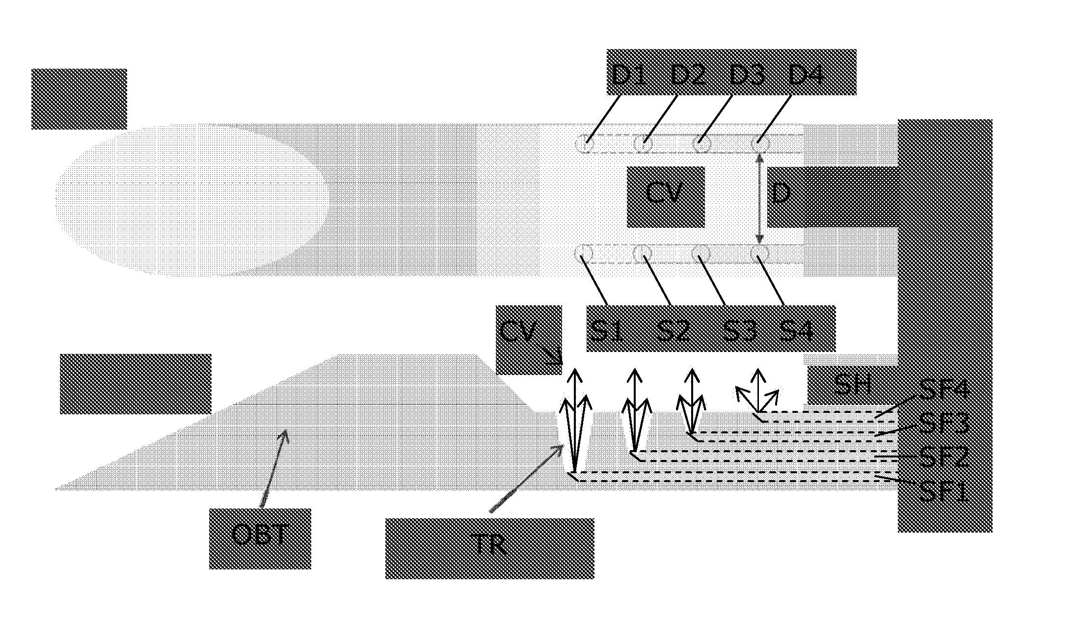
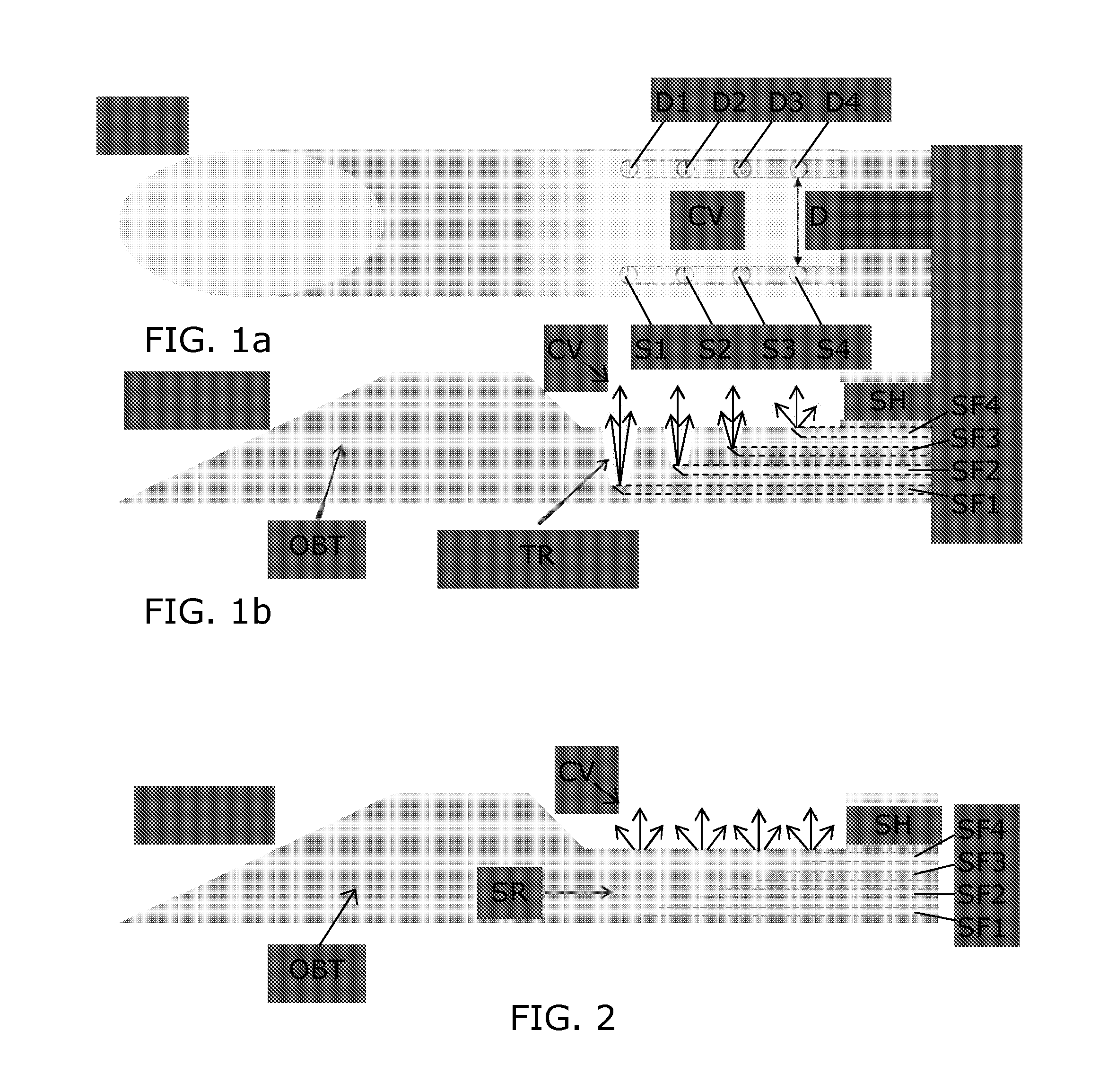
[0051]In the prior art, Vacuum Assisted Biopsy (VAB) needle or cannula are known, e.g. available from Devicor Medical Products, e.g. for performing biopsy in treating and diagnosing breast cancer. In such devices small sucking holes are embedded at the bottom of a notch forming a cavity in the interventional structure, which allow for sucking tissue into the cavity for facilitating the tissue cutting. A larger sucking hole adjacent to the cavity is then used for removing the cut tissue volume from the notch. In a normal procedure, the needle is positioned under the lesion. The tissue is then sucked (vacuumed) into the cavity, the tissue is cut by means of a cutter, and after completion of the cutting, the biopt is sucked away from the cavity via the hole adjacent to the cavity, and transported away from the interventional structure. The tissue is sucked into the cavity by applying a negative pressure (underpressure). After having been cut, the tissue is sucked out of the cavity and ...


PUM


Abstract

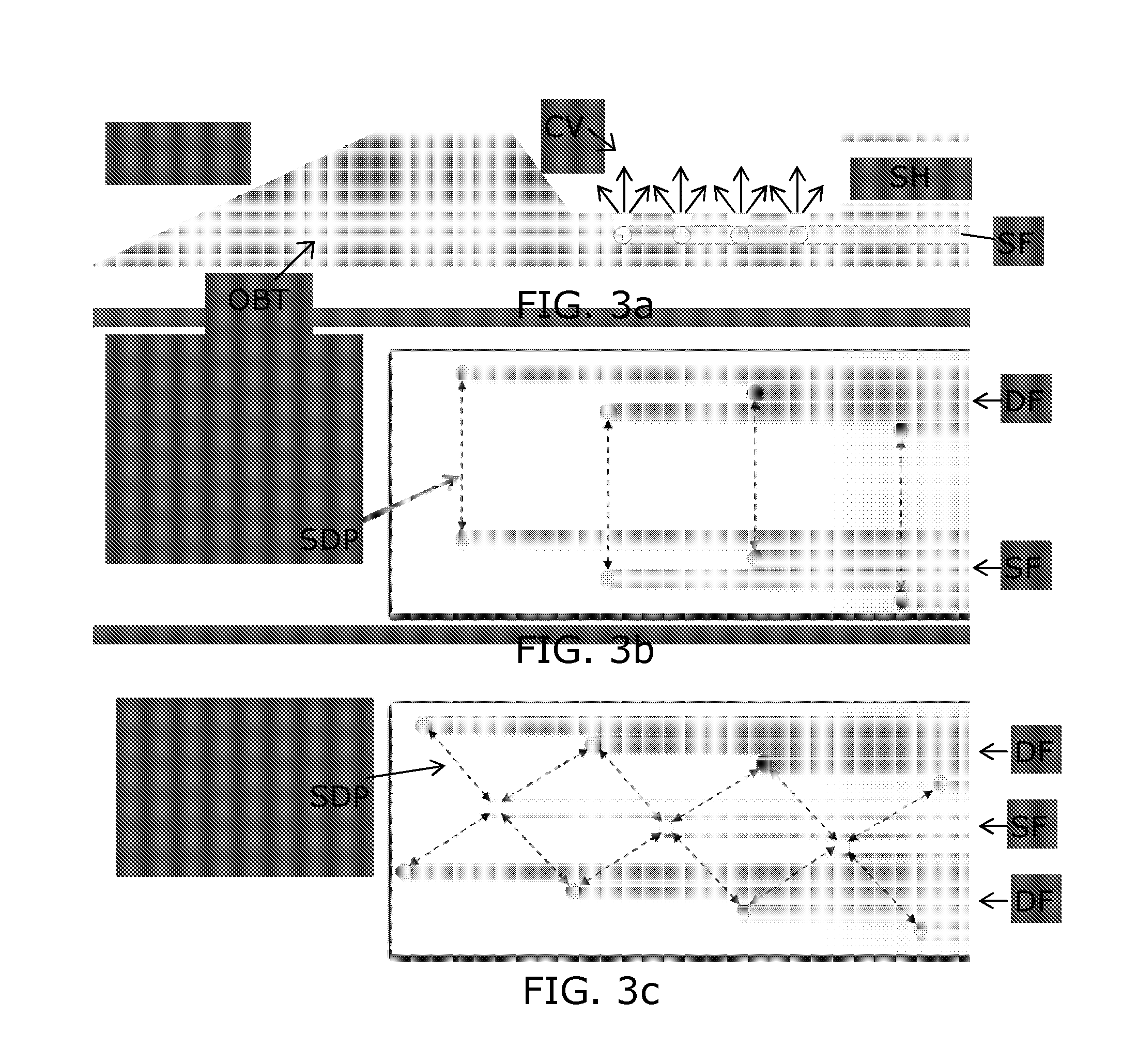
An interventional device, e.g. a Vacuum Assisted Biopsy (VAB) needle, incorporating optical fibers such that biological tissue in a volume at a side of the interventional device can be substantially completely optically probed by optical spectroscopy. In a VAB embodiment, a plurality of optical fiber pairs connected to respective optical ports, are placed at opposite positions along the suction cavity, and they are readout subsequently allowing to make a map of the tissue properties along the place where the tissue will be cut by the VAB needle. Based on decision software in an optical console, it can be determined whether the tissue present in the cutting cavity is completely normal tissue or not, prior to actually performing the biopsy on the tissue. In this way a well defined end point for VAB is created. In one embodiment, the optical fibers are arranged in a wall structure of a thin sleeve which fits onto existing VAB needles, thus allowing the VAB needle to be upgraded with an optical probing capability.

Description

FIELD OF THE INVENTION[0001]The present invention relates to the field of medical devices, equipment, interventional devices, and surgical tools. More specifically, the invention relates to a vacuum assisted biopsy device with optical guiding means.BACKGROUND OF THE INVENTION[0002]In order to diagnose breast cancer, breast biopsies are performed. Various types of breast biopsy exist such as fine needle aspiration (FNA), core needle biopsy (CNB) which can be performed under ultrasound or under X-ray guidance (stereotactic biopsy), vacuum-assisted biopsy (VAB), incisional biopsy (IB) or an excisional biopsy (EB). In a FNA a thin needle is used to harvest a small amount of cells for cytological inspection. In a core needle biopsy typically a 16 or 14 gauge biopsy needle is used to obtain a tissue specimen that allows histological investigation. Typically more than one biopsy is taken per procedure in order to obtain sufficient tissue that allows staging of the tumor (in situ versus inv...

Claims


Application Information

Patent Timeline
IPC IPC(8): A61B10/04A61B10/02A61B17/34A61B5/00
CPCA61B10/04A61B5/0084A61B10/0275A61B2562/0233A61B2010/045A61B2017/00199A61B2017/00907A61B17/3403A61B5/0075A61B5/6848A61B10/0041A61B10/0283A61B2010/0225A61B2017/00057A61B2017/008A61B2017/320064A61B2505/05
Inventor HENDRIKS, BERNARDUS HENDRIKUS WILHELMUSREICH, CHRISTIANBIERHOFF, WALTHERUS CORNELIS JOZEFMUELLER, MANFREDVAN GAAL, FRANCISCUS MARINUS ANTONIUS MARIAVERSLEEGERS, JOZEF CHRISTIAAN MATHIEUPULLY, VISHNU VARDHANSTOFFELEN, SVEN
Owner KONINKLJIJKE PHILIPS NV
Learn More