
Method for manufacturing of three-dimensional freestanding porous thin-graphite with hierarchical porosity

a manufacturing method and porous thin-graphite technology, applied in the field of three-dimensional manufacturing, can solve the problems of reducing the actual available surface area, difficult control of graphene sheets, and lowering device performance, and achieves the effect of improving the conductivity of the graphite structure with 2 m porosity and enhancing chemical vapor deposition or sputtering

Inactive Publication Date: 2015-12-17
BOARD OF RGT THE UNIV OF TEXAS SYST
View PDF0 Cites 34 Cited by
  • Summary
  • Abstract
  • Description
  • Claims
  • Application Information

AI Technical Summary

Benefits of technology

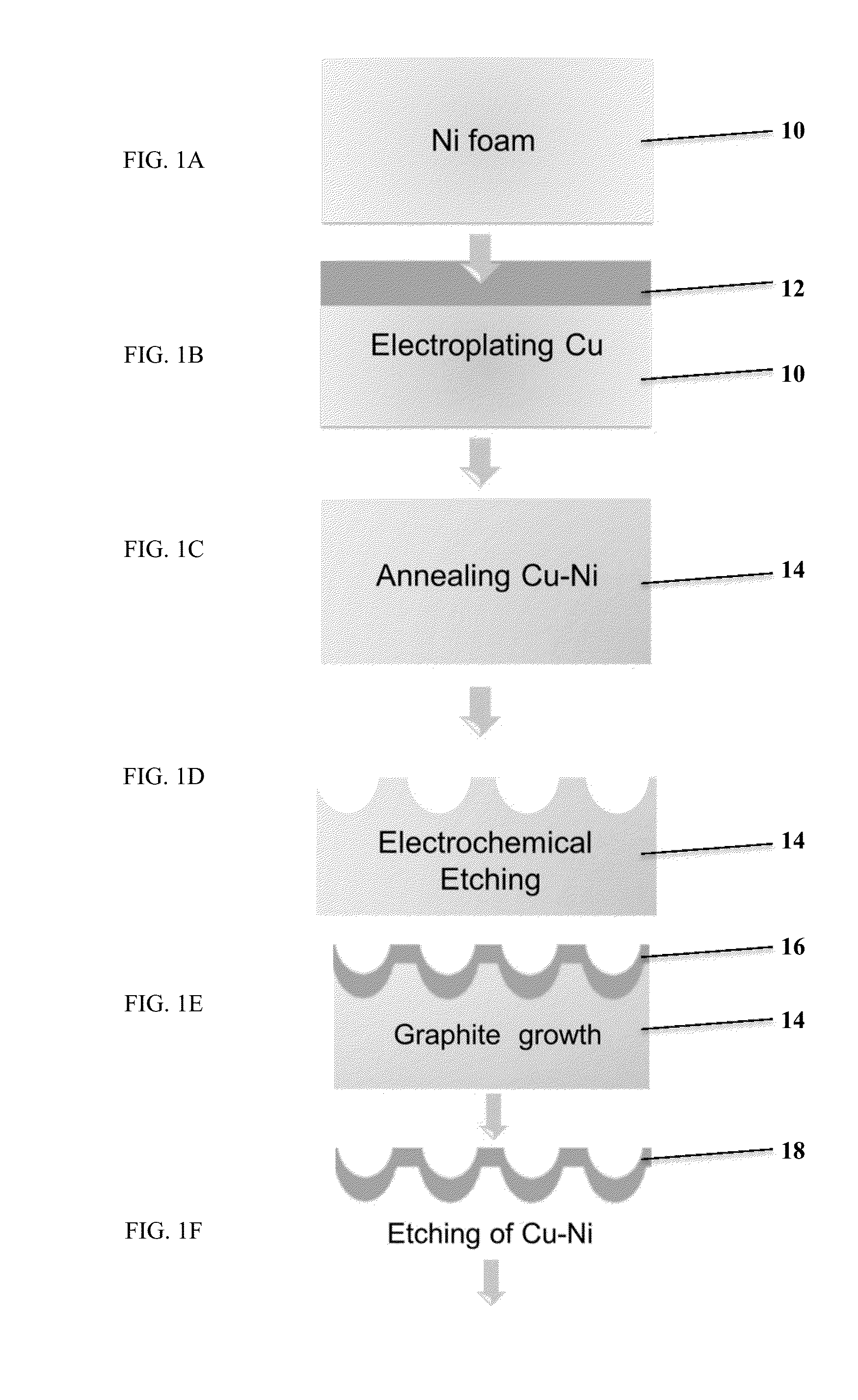
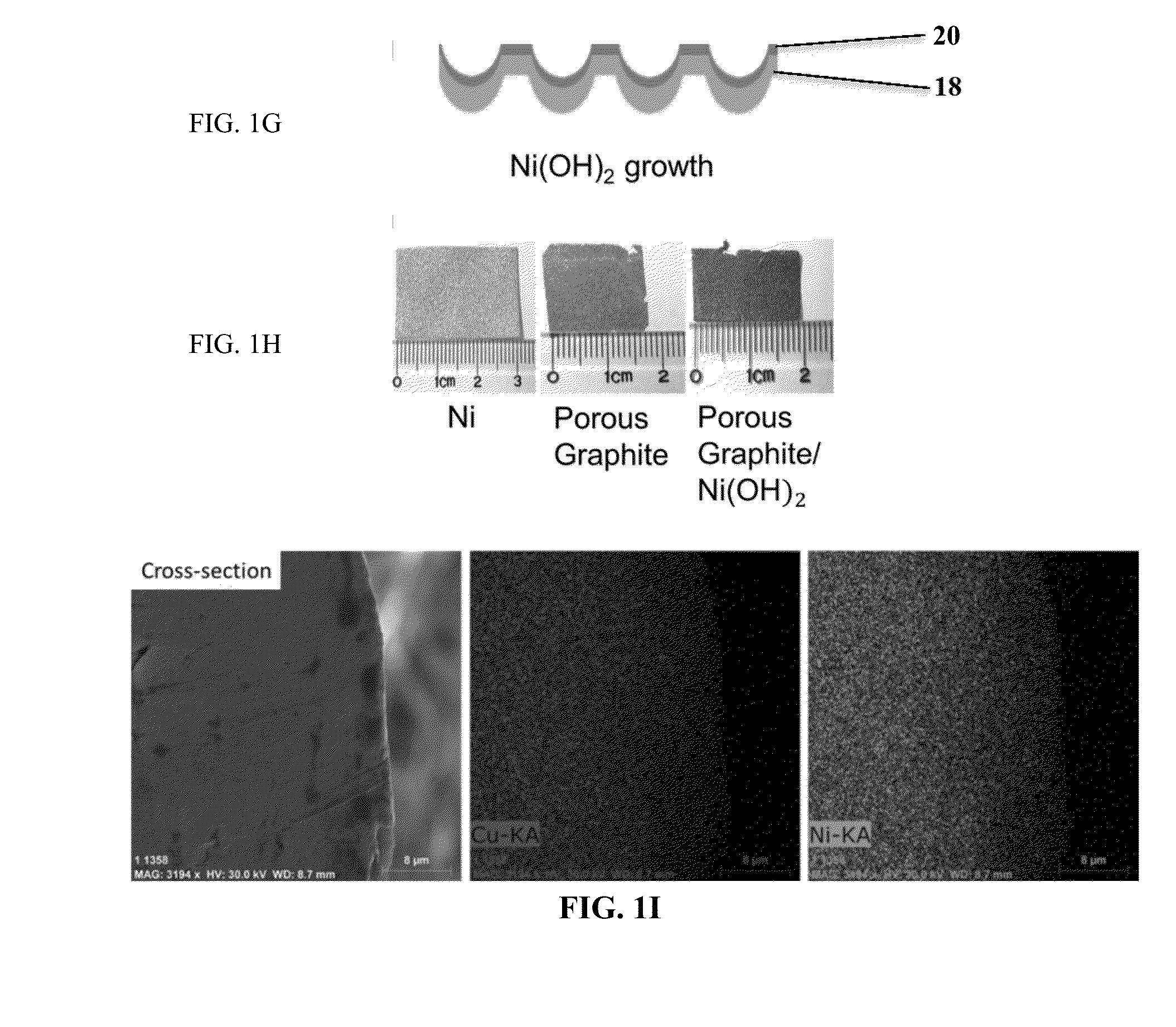
The present invention provides a method for making a three-dimensional graphite structure with controlled porosity. The method involves plating a metal layer on a foam substrate, annealing the metal and foam into a porous metal-nickel, iron, or cobalt catalyst, etching the smooth surface of the catalyst, growing a carbonaceous layer on the porous surfaces of the catalyst, and completely etching the catalyst to obtain the graphite layer. The resulting graphite structure has a smooth surface and embedded porous microstructures that can be readily exposed. The method can be used to make electrodes for metal hydroxide supercapacitors. The conductivity of the graphite structure is improved by three times when compared to that of a smooth surface. The carbonaceous layer can be formed into an electrode support for metal hydroxide supercapacitors. The method also allows for adjusting the porosity of the foam substrate and growing at least one of a metal hydroxide, oxide, or sulfide layer on the graphite layer.

Problems solved by technology

However, it remains a challenge to rationally and efficiently synthesize carbonaceous materials into 3-D porous nanosuperstructures, which boast both high specific surface areas and fast ionic transports that significantly improve the performance of energy devices.
Nevertheless, the assembly of graphene sheets is difficult to control, which could reduce the actual available surface areas and thus lower the device performance21.
Nevertheless, it remains extremely difficult to achieve 3-D carbonaceous nanostructures with multilevel porosity, which promises high surface areas and enhanced ionic transport24.

Method used


Image

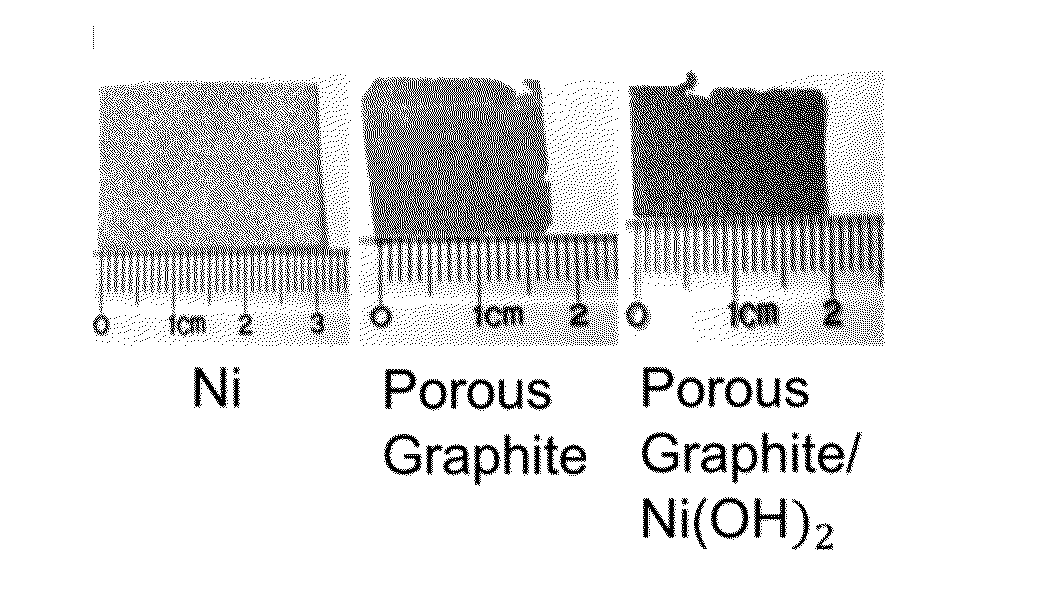
  • Method for manufacturing of three-dimensional freestanding porous thin-graphite with hierarchical porosity
  • Method for manufacturing of three-dimensional freestanding porous thin-graphite with hierarchical porosity
  • Method for manufacturing of three-dimensional freestanding porous thin-graphite with hierarchical porosity

Examples


Embodiment Construction

[0023]While the making and using of various embodiments of the present invention are discussed in detail below, it should be appreciated that the present invention provides many applicable inventive concepts that can be embodied in a wide variety of specific contexts. The specific embodiments discussed herein are merely illustrative of specific ways to make and use the invention and do not delimit the scope of the invention.

[0024]To facilitate the understanding of this invention, a number of terms are defined below. Terms defined herein have meanings as commonly understood by a person of ordinary skill in the areas relevant to the present invention. Terms such as “a”, “an” and “the” are not intended to refer to only a singular entity, but include the general class of which a specific example may be used for illustration. The terminology herein is used to describe specific embodiments of the invention, but their usage does not delimit the invention, except as outlined in the claims.

[...


PUM

PropertyMeasurementUnit
feature sizeaaaaaaaaaa
thicknessaaaaaaaaaa
temperatureaaaaaaaaaa

Abstract

The present invention includes an apparatus and a method of making a three dimensional graphite structure with a controlled porosity comprising: plating a metal layer on at least one of a nickel, an iron or a cobalt foam substrate; annealing the metal and the nickel, iron or cobalt foam into a porous metal-nickel, iron or cobalt catalyst, wherein the catalyst has a smooth and a porous surface; etching the smooth surface of the annealed porous metal-nickel, iron or cobalt catalyst; growing a carbonaceous layer on the porous surface of the annealed porous metal-nickel, iron or cobalt catalyst; and completely etching the porous metal-nickel, iron or cobalt catalyst to obtain the graphite layer.

Description

CROSS-REFERENCE TO RELATED APPLICATIONS[0001]This application claims benefit of U.S. Provisional Application Ser. No. 62 / 011,383 filed Jun. 12, 2014, which is incorporated herein by reference in its entirety.STATEMENT OF FEDERALLY FUNDED RESEARCH[0002]This invention was made with government support under Grant No. CMMI1150767 awarded by the National Science Foundation. The government has certain rights in the invention.TECHNICAL FIELD OF THE INVENTION[0003]The present invention relates in general to the field of three-dimensional manufacturing, and more particularly, to a novel method for manufacturing of three-dimensional freestanding porous thin-graphite with hierarchical porosity.BACKGROUND OF THE INVENTION[0004]Without limiting the scope of the invention, its background is described in connection with three-dimensional carbon-based structures.[0005]The fast depletion of fossil energy and the associated adverse environmental impacts make it highly desirable to explore renewable-e...

Claims


Application Information

Patent Timeline
Patent Type & Authority Applications(United States)
IPC IPC(8): C01B31/04H01G13/06
CPCH01G13/06C01B31/04C01P2006/40C01B32/20C01B32/205C01B32/21H01G11/24H01G11/32H01G11/86Y02E60/13
Inventor FAN, DONGLEINING, JINGXU, XIAOBINGUO, JIANHE
Owner BOARD OF RGT THE UNIV OF TEXAS SYST
Learn More