Solar cell module production method

Inactive Publication Date: 2015-12-17
PANASONIC INTELLECTUAL PROPERTY MANAGEMENT CO LTD
View PDF10 Cites 2 Cited by
  • Summary
  • Abstract
  • Description
  • Claims
  • Application Information

AI Technical Summary

Benefits of technology

[0006]According to the present invention, it is possible to improve the performance of a solar cell module, for examp

Problems solved by technology

However, the effects of heat during soldering can cause warping and cracking of the

Method used


Image

  • Solar cell module production method
  • Solar cell module production method
  • Solar cell module production method

Examples


Embodiment Construction

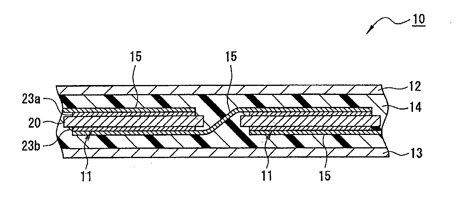
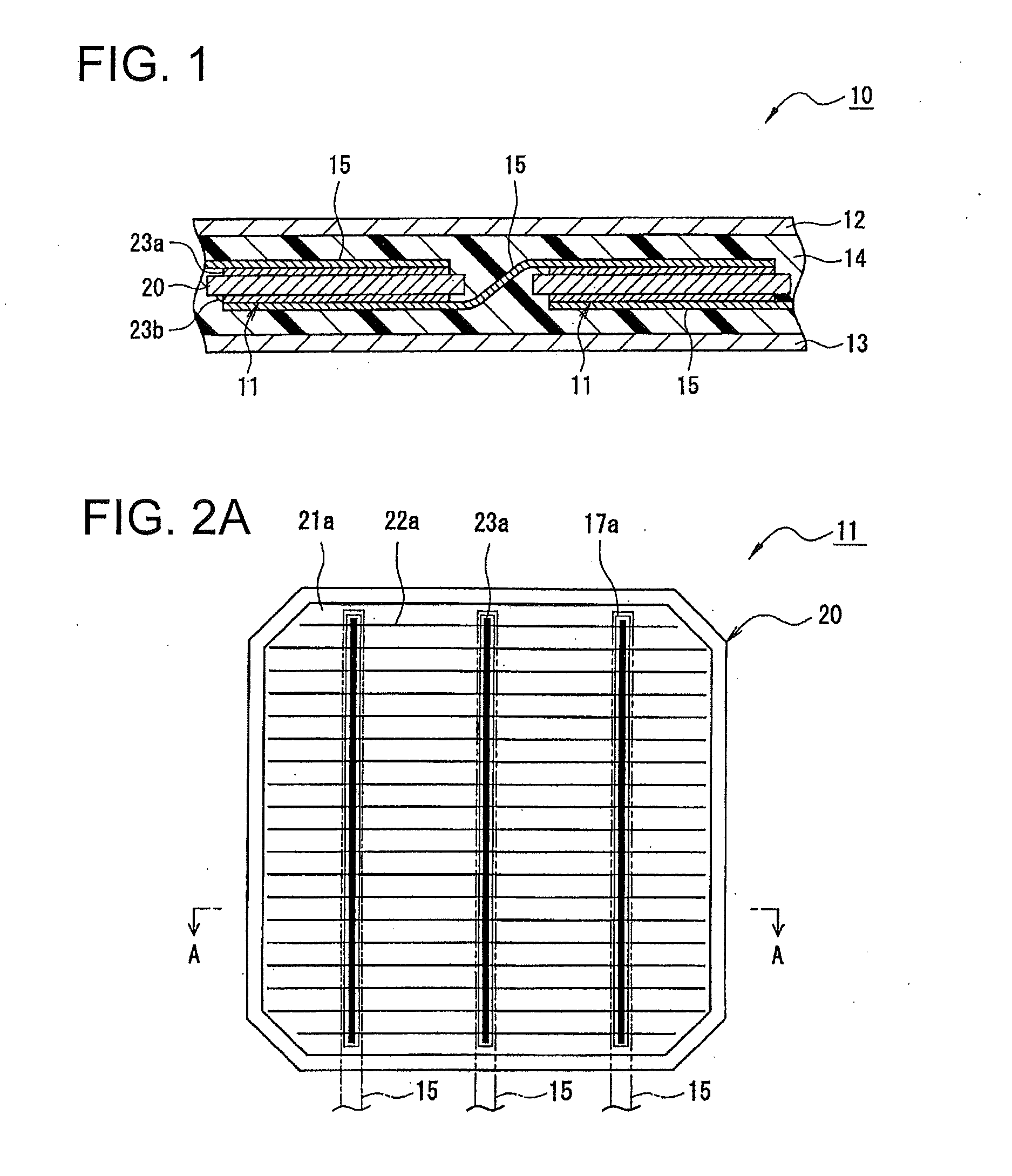
[0020]In the following, embodiments according to the present invention will be described in detail with reference to the drawings.

[0021]The drawings to be referred to in the embodiments are schematically described, and the dimensional ratios etc. of the components depicted in these drawings may be different from those of the actual components. The specific dimensional ratios etc. should be determined in consideration of the following description.

[0022]In this specification, a “light-receiving surface” means a surface through which sunlight mainly enters from the outside of a solar cell. A “rear surface” means a surface opposite to the light-receiving surface. To be more specific, more than 50% to 100% of the sunlight entering the solar cell enters from the light-receiving surface side.

[0023]Unless otherwise noted, an “upper side” means the vertically upper side.

[0024]To take “substantially the same” for example, it is intended that the word “substantially” refers not only to being c...


PUM


Abstract

A solar cell module production method involves applying adhesives on a light-receiving surface and a rear surface of a solar cell having electrodes on the light-receiving surface and the rear surface, and positioning and attaching a wiring material on the adhesives. Specifically, the adhesives are applied via screen printing, and different screen plates are used on the light-receiving surface side and the rear surface side to apply a greater amount of adhesive on the rear surface side than on the light-receiving surface side.

Description

CROSS-REFERENCE TO RELATED APPLICATION[0001]The present application is a continuation under 35 U.S.C. §120 of PCT / JP2014 / 000654, filed Feb. 7, 2014, which is incorporated herein by reference and which claimed priority to Japanese Patent Application No. 2013-039778 filed Feb. 28, 2013. The present application likewise claims priority under 35 U.S.C. §119 to Japanese Patent Application No. 2013-039778 filed Feb. 28, 2013, the entire content of which is also incorporated herein by reference.TECHNICAL FIELD[0002]The present invention relates to a solar cell module production method.BACKGROUND ART[0003]A solar cell module includes a plurality of solar cells, a wiring material which connects the solar cells with one another, and an encapsulant which seals these solar cells and wiring material, and the like. The wiring material is bonded on electrodes of the solar cell, and solder has been mainly used for this bonding. However, the effects of heat during soldering can cause warping and cra...

Claims


Application Information

Patent Timeline
IPC IPC(8): H01L31/0224H01L31/18H01L31/05
CPCH01L31/022425H01L31/18H01L31/0504B41M3/006B41P2215/50Y02E10/50
Inventor SUZUKI, SATOSHIKUDOH, YOSHIYUKINAKAI, MASAYA
Owner PANASONIC INTELLECTUAL PROPERTY MANAGEMENT CO LTD
Why Eureka
Try Eureka